| GENX-1B CLEANING,INSPECTION,AND REPAIR MANUAL | Dated: 11/26/2021 | |
| CIR 72-58-40 , REPAIR 005 | ||
| MID FAN SHAFT - REPAIR - FLANGE AREA MACHINING REPAIR | ||
| GENX-1B CLEANING,INSPECTION,AND REPAIR MANUAL | Dated: 11/26/2021 | |
| CIR 72-58-40 , REPAIR 005 | ||
| MID FAN SHAFT - REPAIR - FLANGE AREA MACHINING REPAIR | ||
| * * * FOR ALL |
| TASK 72-58-40-300-805 |
| 1 . | Flange Area Machining Repair. |
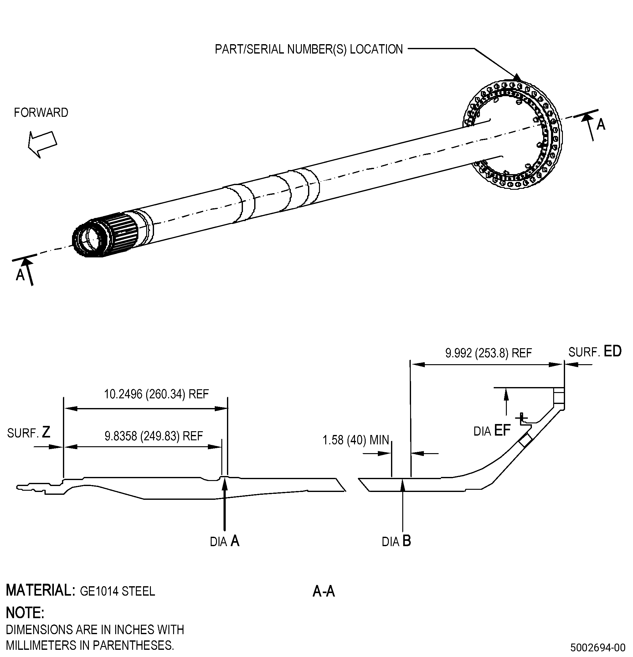
| A. | This procedure gives instructions to repair the mid fan shaft (shaft) by machining the flange area to remove surface defects. Refer to Figure 901. |
| B. | The following maximum repairable limits apply to this repair: |
| NOTE: |
|
| NOTE: |
|
| (4) | Visual Inspection. |
| (k) | Do an inspection of the mounting flange for: |
| 2 | Nicks, dents, or scratches: |
| Maximum repairable limit: |
|
| 3 | Corrosion pit: |
| Maximum repairable limit: |
|
| 4 | Nicks, dents, or scratches on the flange face: |
| Maximum repairable limit: |
|
| 5 | Fretting or galling in area Y on the forward flange face: |
| Maximum repairable limit: |
|
| 6 | Fretting or galling in all other areas on the forward flange face: |
| Maximum repairable limit: |
|
| 7 | Fretting or galling on the aft flange face: |
| Maximum repairable limit: |
|
| 8 | Corrosion pit on the flange face: |
| Maximum repairable limit: |
|
| (m) | Do an inspection of the seal air flange for: |
| 2 | Nicks, dents, and scratches: |
| Maximum repairable limit: |
|
| 3 | Corrosion pits: |
| Maximum repairable limit: |
|
| C. | The subsequent table gives a list of the part numbers that are applicable to this repair. All part numbers are applicable to all paragraphs unless specified differently. |
|
|||||||||||||||||||||||||||||||||||||||||||||||||
| D. | Proprietary/Complex Process Statement. |
| (1) | None. |
| 2 . | Tools, Equipment, and Materials. |
| NOTE: |
|
| A. | Tools and Equipment. |
| (1) | Special Tools. None. |
| (2) | Standard Tools and Equipment. None. |
| (3) | Locally Manufactured Tools. None. |
| B. | Consumable Materials. None. |
| C. | Referenced Procedures. |
| D. | Expendable Parts. None. |
| E. | SPD Information. |
| (1) | Locally Manufactured SPD. None. |
| F. | Special Solutions. None. |
| G. | Test Specimens. None. |
| 3 . | Dimensional Information. |
| Subtask 72-58-40-220-089 |
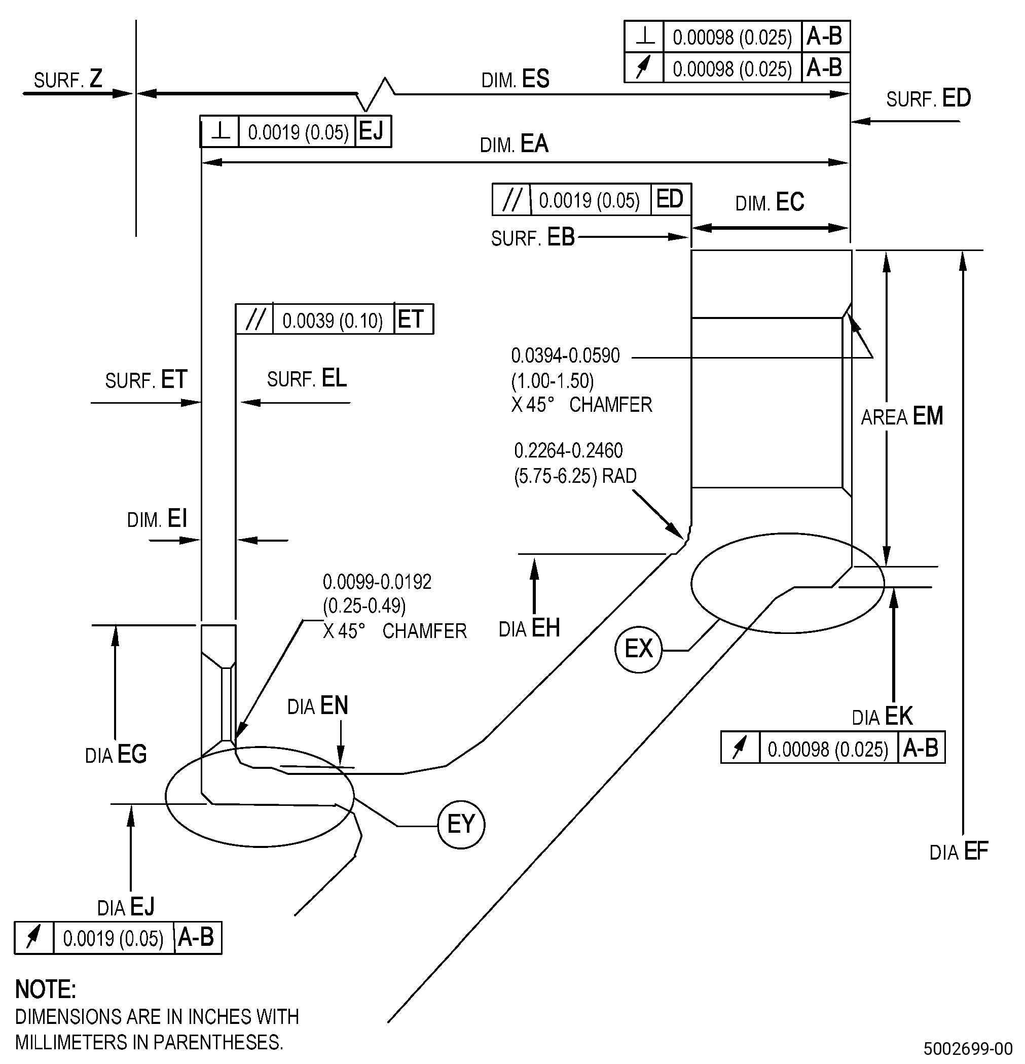
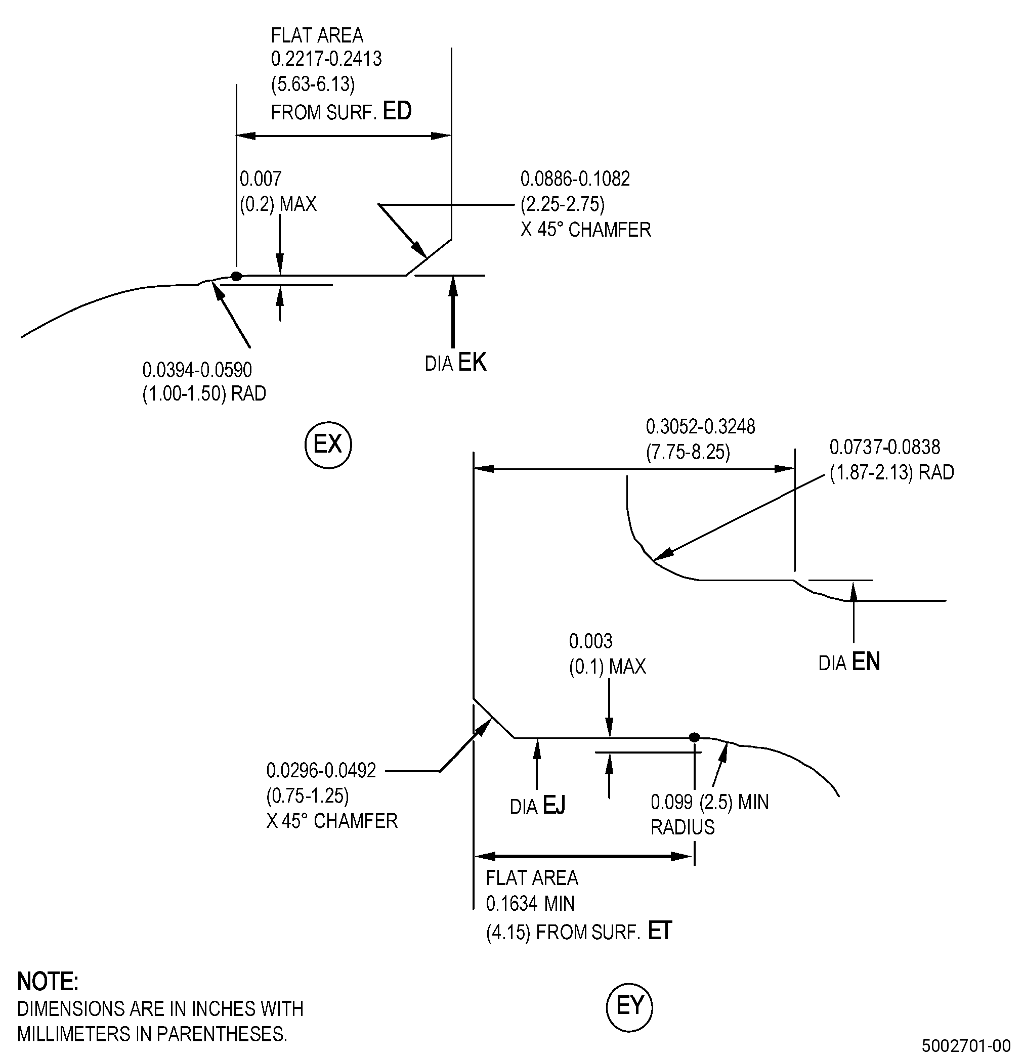
| A. | Refer to Figure 901 and Figure 902 for specified dimensions and locations. |
| NOTE: |
|
| NOTE: |
|
|
| 4 . | Setup Information. |
| Subtask 72-58-40-350-025 |
| A. | Set-up the shaft for machining. Refer to Figure 901 and as follows: |
| (1) | Install the shaft on the machine and/or fixture as follows: |
| (a) | You can use the conical centering surfaces on the shaft two ends. |
| (2) | Adjust the shaft position until diameter A and diameter B runout is 0.00047 inch (0.012 mm) or less. |
| 5 . | Procedure. |
| Subtask 72-58-40-350-026 |
| CAUTION: |
|
| A. | If it is not possible to do this repair in 24 hours or less, apply protective oil to prevent corrosion of the shaft. Refer to TASK 72-58-00-550-801 (72-58-00, STORAGE 001). |
| Subtask 72-58-40-160-002 |
| B. | If necessary, clean the shaft. Refer to TASK 72-58-40-100-801 (72-58-40, CLEANING 001). |
| Subtask 72-58-40-220-090 |
| C. | Do a dimensional inspection of the shaft area that you will machine. Refer to Subtask 72-58-40-220-089 (paragraph 3.A.), Dimensional Information and Figure 902. |
| Subtask 72-58-40-350-027 |
| D. | If necessary, read and record all identity marks on the shaft outer diameter EF surface. Refer to Figure 901 and as follows: |
| (1) | Recording of the marks is necessary when you machine the shaft diameter EF. |
| (2) | It is necessary to record the shaft marking letters, marking values (if numerical marking), marking location, and font size if marking is necessary in Subtask 72-58-40-350-028 (paragraph 5.K.). |
| Subtask 72-58-40-350-030 |
| (3) | Shaft identification marks that you will record must include the information that follows: |
| (a) | Part or assembly identification number. |
| (b) | Manufacturer identification number. |
| (c) | Service bulletin identification (if necessary). |
| (d) | Part serial number. |
| (e) | T mark at the 12 o'clock position. |
| (f) | Shaft length from surface Z to surface ED marked as xxx.xx mm. |
| (g) | Location of L, surface ED lowest runout. |
| Subtask 72-58-40-350-031 |
| E. | If it is necessary to machine the shaft surface ET or surface EL, remove all the shank nuts. Refer to TASK 72-58-40-300-802 (72-58-40, REPAIR 004). |
| Subtask 72-58-40-320-005 |
| CAUTION: |
|
| F. | Machine surface EB, surface ED, surface EL, surface ET, diameter EF, diameter EG, diameter EJ, diameter EK, and diameter EN of the shaft to remove all the damage in the repair area. Refer to TASK 70-00-03-800-004 (MACHINING DATA), Subtask 72-58-40-220-089 (paragraph 3.A.), Dimensional Information, Figure 902, and as follows: |
| (1) | Set-up the shaft for machining. Refer to Subtask 72-58-40-350-025 (paragraph 4.A.), Setup Information. |
| (2) | Machine the shaft to remove all defects in the repair area as follows: |
| Subtask 72-58-40-220-091 |
| (a) | Make sure that you remove only a minimum quantity of material necessary to remove the surface defects. |
| (b) | Make sure that all dimensions stay in the limits of Subtask 72-58-40-220-089 (paragraph 3.A.), Dimensional Information, Figure 902, and as follows: |
| 1 | During the machining of surface ED, make sure that dimension ES, dimension EA, and dimension EC all stay in tolerance. |
| (3) | Surface finish of the shaft diameter EK must be 31 microinches (0.8 micrometers) or better. |
| (4) | Surface finish of surface ED, surface ET, diameter EJ, and diameter EN of the shaft must be 63 microinches (1.6 micrometers) or better. |
| (5) | Unless specified differently, make sure that the shaft surface finish is 91 microinches (2.3 micrometers) or better. |
| Subtask 72-58-40-320-004 |
| (6) | Machine the chamfer at the boltholes, on the shaft surface ED, surface EL, and surface ET. |
| (7) | Break all sharp edges and corners at the shaft repair areas, but not at the chamfer, to 0.00500-0.01500 inch (0.127-0.381 mm). |
| (8) | Break all sharp edges and corners of the chamfer at the shaft repair areas to a maximum radius of 0.01000 inch (0.254 mm). |
| (9) | Remove the shaft from the machine and/or fixture. |
| Subtask 72-58-40-240-002 |
| CAUTION: |
|
| CAUTION: |
|
| G. | Alternative Procedure Available. Do a magnetic-particle inspection of the shaft repaired areas. Refer to TASK 72-58-40-200-801 (72-58-40, INSPECTION 001). |
| NOTE: |
|
| Subtask 72-58-40-220-130 |
| G.A. | Alternative Procedure. Do an inspection of the shaft machined areas as follows: |
| Subtask 72-58-40-110-012 |
| (1) | Etch the shaft machined areas. Refer to TASK 70-24-00-110-033 (ETCHING PROCEDURES FOR FLUORESCENT-PENETRANT INSPECTION), TASK 70-24-01-110-034 (SWAB ETCHING PROCEDURE), and as follows: |
| (a) | Use Class C etchant. |
| Subtask 72-58-40-230-003 |
| (2) | Do an inspection of the shaft machined areas. Refer to TASK 70-32-00-200-002 (INDIRECT INSPECTION METHODS), TASK 70-32-03-230-002 (SPOT-FLUORESCENT-PENETRANT INSPECTION), and as follows: |
| (a) | Use Class D penetrant. |
| (b) | Indications are not permitted. |
| Subtask 72-58-40-380-008 |
| H. | Peen the shaft repaired areas. Refer to TASK 70-47-01-380-016 (SHOTPEENING) and as follows: |
| (1) | Use media size equivalent to S170 or smaller. |
| (2) | Shot media hardness must be 55-65 HRC. |
| (3) | Peening intensity must be 0.010-0.015A. |
| (4) | Minimum of 100 percent coverage is necessary. |
| Subtask 72-58-40-220-092 |
| I. | Do a dimensional inspection and a visual inspection of the shaft machined areas. Refer to Subtask 72-58-40-220-089 (paragraph 3.A.), Dimensional Information, Figure 901, Figure 902, and as follows: |
| (1) | Make sure that all the dimensions in the shaft machined areas agree with the specified limits. |
| Subtask 72-58-40-220-094 |
| (2) | If you repaired the shaft surface ED, measure the distance between surface Z and surface ED as follows: |
| (a) | The measured reading must be accurate to four decimal places in inches (two decimal places in millimeters). |
| (b) | If the shaft actual length is measured in inches, convert the value into millimeters and round to hundredths of a millimeter. |
| Subtask 72-58-40-350-032 |
| (3) | If you repaired the shaft surface ED, record the measured lowest runout point of surface ED with respect to diameter A and diameter B. |
| Subtask 72-58-40-380-009 |
| WARNING: |
|
| J. | If you repaired the shaft surface ED, clean the flange area EM to increase the coefficient of friction. Refer to TASK 70-47-03-380-018 (DRY ABRASIVE BLAST SURFACE FINISHING) and as follows: |
| (1) | Use grit size of 150-220 mesh. |
| (2) | Use nozzle pressure of 28-57 psi (194-393 kPa). |
| (3) | Use a nozzle-to-surface distance of 3.94-5.90 inches (100-150 mm) and an angle of 40-60 degrees from the shaft surface. |
| Subtask 72-58-40-350-028 |
| K. | Put a mark on the shaft diameter EF. Refer to TASK 70-16-00-350-001 (MARKING PRACTICES), TASK 70-16-08-350-001 (DOT PEEN MARKING FOR OPTICAL CHARACTER RECOGNITION), and as follows: |
| Subtask 72-58-40-210-001 |
| (1) | Do a check for the shaft mark information that is changed, illegible, or fully removed. Refer to Subtask 72-58-40-350-030 (paragraph 5.D.(3)). |
| Subtask 72-58-40-350-029 |
| (2) | Line-out the remaining marks on the shaft surface EF that are changed or illegible as follows: |
| NOTE: |
|
| (a) | Line-out the remaining markings with two lines. |
| (3) | Put a mark on the shaft surface EF for markings that are changed or fully removed. Refer to Figure 901, Figure 902, and as follows: |
| (a) | Marking information is listed in Subtask 72-58-40-350-030 (paragraph 5.D.(3)) and as follows: |
| 1 | If surface ED is repaired, refer to Subtask 72-58-40-220-094 (paragraph 5.I.(2)) and Subtask 72-58-40-350-032 (paragraph 5.I.(3)). |
| (b) | Put the markings, but not the T and L markings, adjacent to the initial markings. |
| (c) | For markings that are fully removed, put the new markings adjacent to their initial location. |
| (d) | Put the mark T as follows: |
| 1 | You must put the mark T back in its initial position or else it will change the circumferential position of the flange during balancing of the shaft. |
| (e) | Put the mark L as follows: |
| 1 | You must not put the mark L again, if surface ED is not repaired, or else the position of the lowest runout of the flange will be inaccurate. |
| 2 | If surface ED is repaired, put the mark L at the position of the lowest runout. Refer to Subtask 72-58-40-350-032 (paragraph 5.I.(3)). |
| (f) | Use method 1 or method 2 and make sure that the markings agree with the initial font size. |