| GENX-1B CLEANING,INSPECTION,AND REPAIR MANUAL | Dated: 03/31/2021 | |
| CIR 72-00-04 , INSPECTION 001 | ||
| LOW PRESSURE TURBINE MODULE ASSEMBLY - INSPECTION | ||
| GENX-1B CLEANING,INSPECTION,AND REPAIR MANUAL | Dated: 03/31/2021 | |
| CIR 72-00-04 , INSPECTION 001 | ||
| LOW PRESSURE TURBINE MODULE ASSEMBLY - INSPECTION | ||
| * * * FOR ALL |
| TASK 72-00-04-200-801 |
| 1 . | General. |
| A. | This procedure gives instructions to do an inspection of the low pressure turbine (LPT) module assembly (LPT module). Refer to Figure 802. |
| • |
|
| • |
|
| • |
|
| (1) | Do this inspection before installation of: |
| • |
|
| • |
|
| • |
|
| B. | Any sub-assembly or part removed for access or limited workscope must be inspected in accordance with criteria in this section. If there is no criteria, the sub-assembly or part must receive a general visual inspection (GVI) for continued serviceability. Refer to TASK 72-00-00-200-805 (72-00-00, INSPECTION 001) . If required, the component can be hand-cleaned to do a visual inspection. Refer to TASK 70-21-01-110-001 (CLEANING METHOD 1 - SOLVENT DEGREASING) or TASK 70-21-03-160-001 (CLEANING METHOD 3 - STEAM CLEANING) . GVI cannot be done to components identified in TASK 05-21-00-200-801 (05-21-00, LIFE LIMITS 001) that become piece part. These components must have their appropriate mandatory inspections done, unless stated differently in an applicable Service Bulletin. |
| C. | If you find an assembly or part to be unserviceable during this procedure, refer to the applicable section of the engine manual for more disassembly and inspection procedures for that assembly or part. |
| D. | If you fully disassemble the LPT module, this inspection is not necessary. Refer to the applicable section of the engine manual for the inspection procedure for each part. |
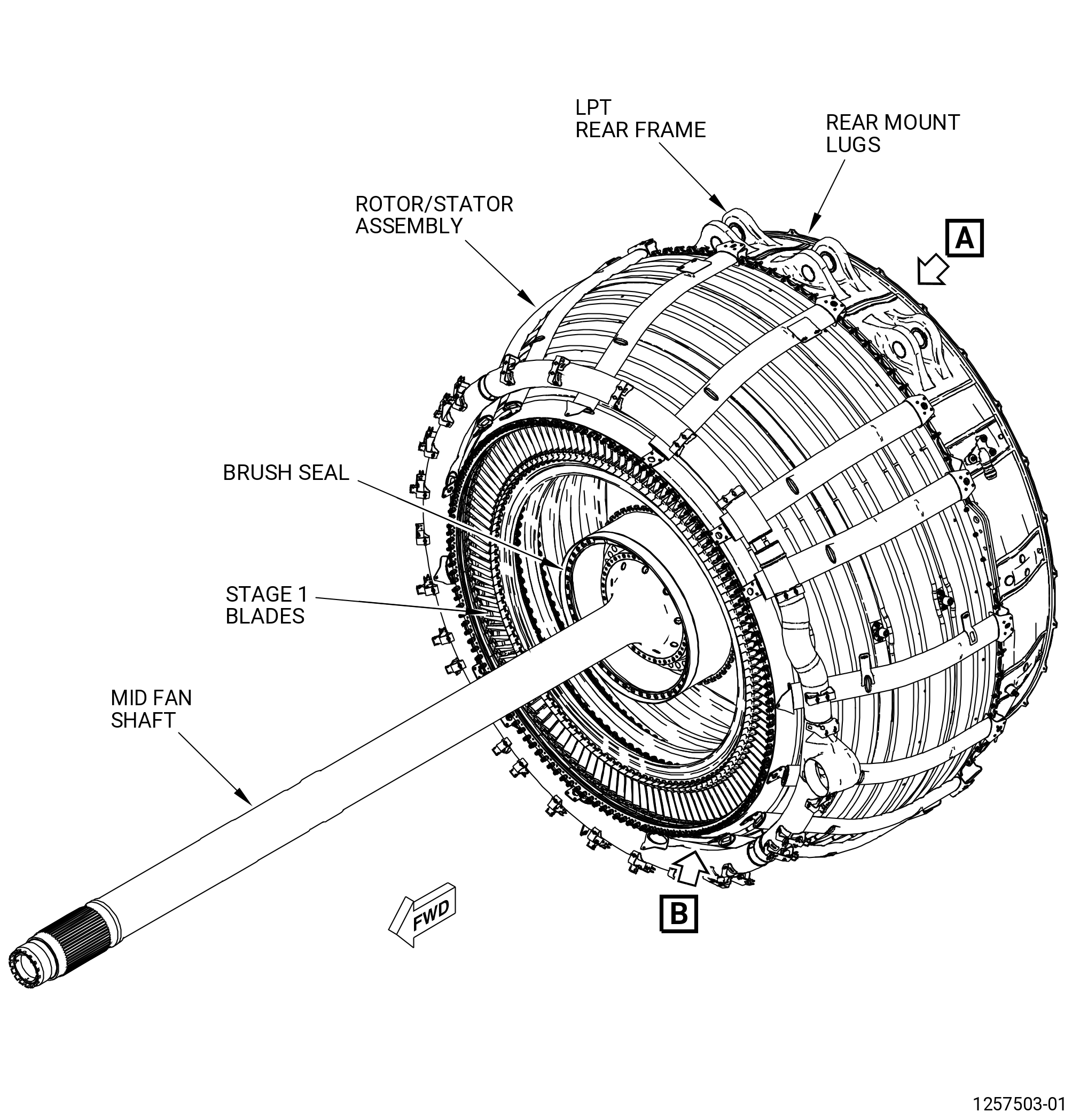
| E. | The major components of the LPT module are: |
| • |
|
| • |
|
| • |
|
| • |
|
| • |
|
| • |
|
| F. | The maintenance instructions in this Manual do not purport to cover all details or variations in equipment, nor do they provide for every possible contingency to be met in connection with installation, operation, maintenance, or GEAE certified repair facilities. The maintenance instructions are intended to be all-inclusive for a complete teardown and overhaul of the component or sub assembly. The individual procedures as written are one sequence based on General Electric experience. Alternate sequences to these maintenance instructions are at the discretion of the operator and/or overhaul shop provided the intent of the maintenance instructions is met. The operator and/or overhaul shop can select specific tasks to partially disassemble and assemble hardware or subassemblies based upon the on demand maintenance requirement of the individual engine work scope provided the final assembly configuration and requirements contained in the manual have been met. |
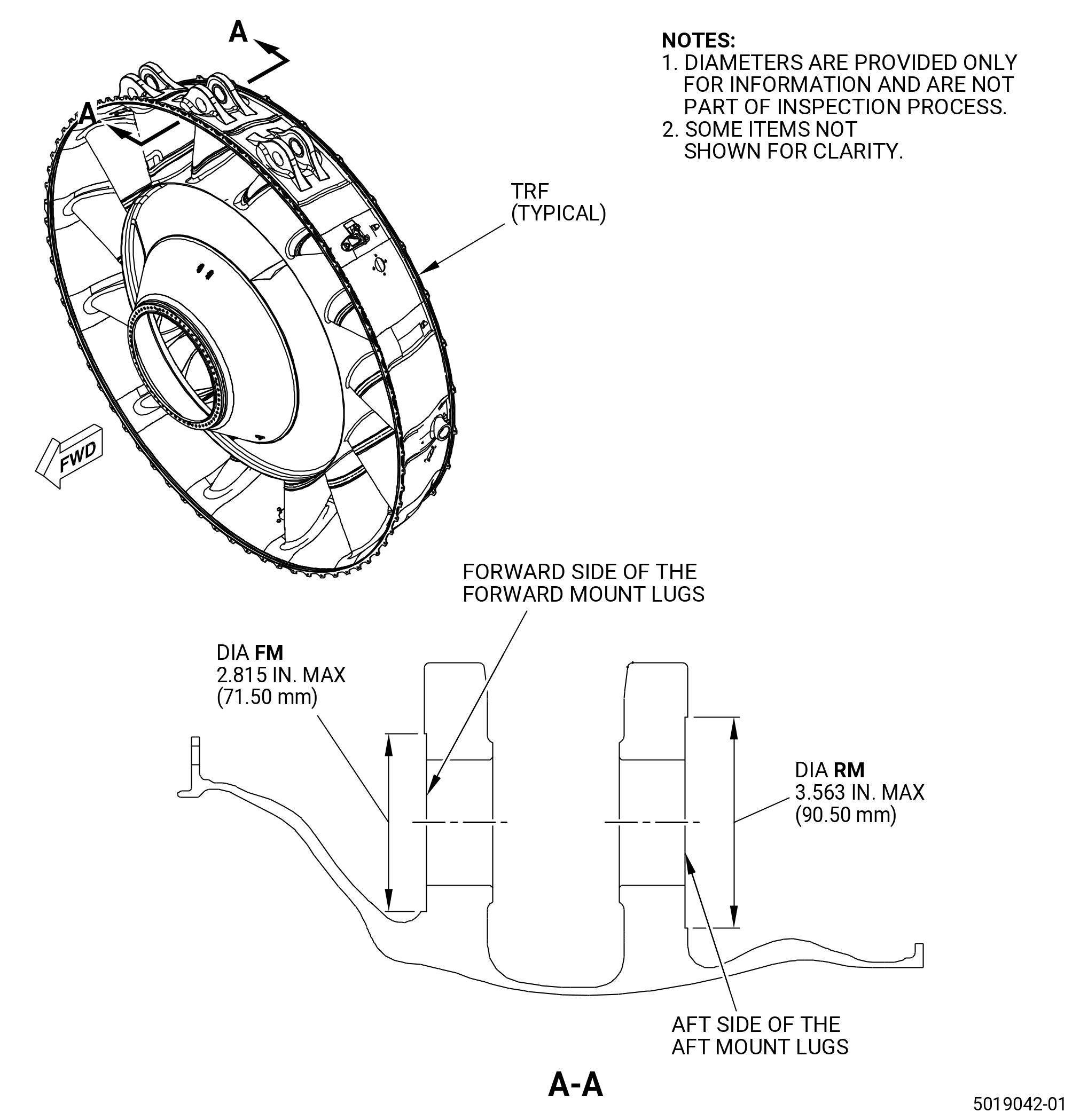
| G. | You can observe the serviceable mount surface irregularities (machined marks around the mount bushings) on the TRF mount lugs: forward side of the forward mount lugs and aft side of the aft mount lugs. The regular production process requires specific clearance between the mounting pin and TRF mount lugs. Make sure that these TRF mount lugs are machined (if necessary) around the mount lug hole. The machining effect can be noticed as a circumferential mark, a single mark or a series of small marks located circumstantially. Usually it is only one mark located on the upper half of the mount lug surface. The machining marks are smooth, shiny and can generate a surface step within specific diameters (FM and RM) from the center of the lug bushing. Refer to Figure 801. |
| NOTE: |
|
| 2 . | Tools, Equipment, and Materials. |
| NOTE: |
|
| A. | Tools and Equipment. |
| (1) | Special Tools. |
|
| (2) | Standard Tools and Equipment. None. |
| (3) | Locally Manufactured Tools. None. |
| B. | Consumable Materials. |
| C. | Referenced Procedures. |
|
| D. | Expendable Parts. None. |
| 3 . | Specific Inspection Procedure. |
| Subtask 72-00-04-230-001 |
| CAUTION: |
|
| A. | Do a fluorescent penetrant inspection (FPI) of the inner and outer surfaces of the LPT rear frame at the rear mount lug locations. |
| Subtask 72-00-04-230-002 |
| * * * PRE SB 72-0063 |
| * * * PRE SB 72-0138 |
| * * * PRE SB 72-0160 |
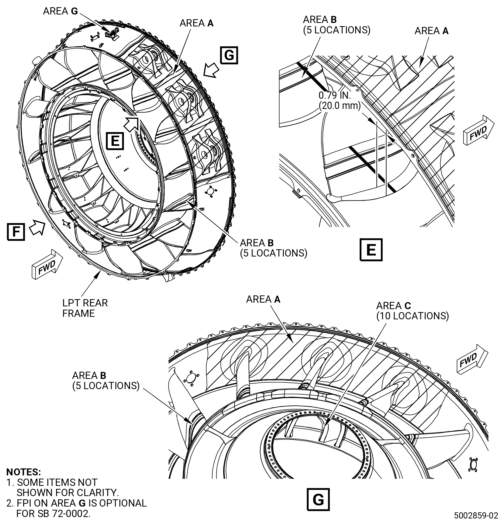
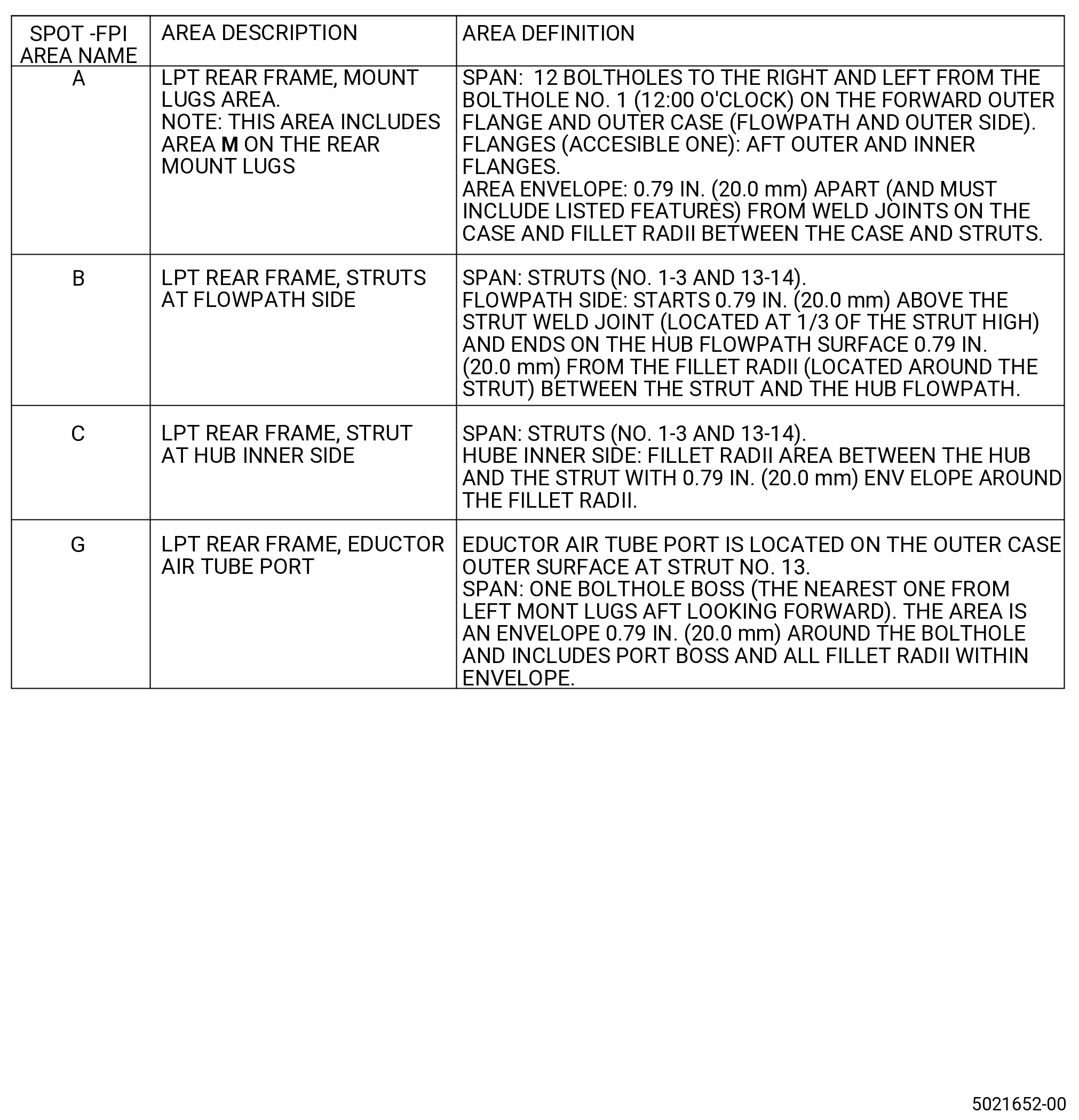
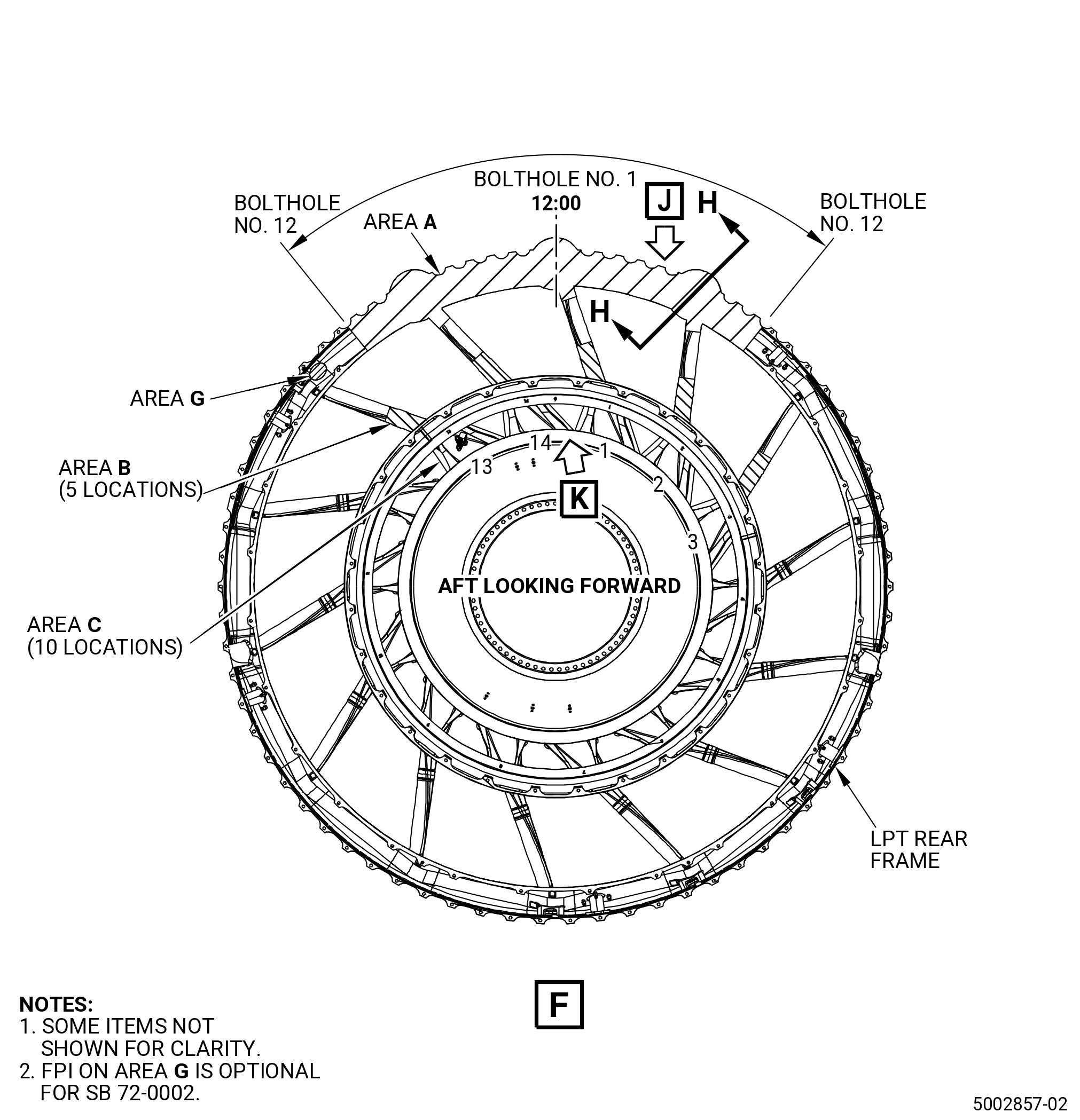
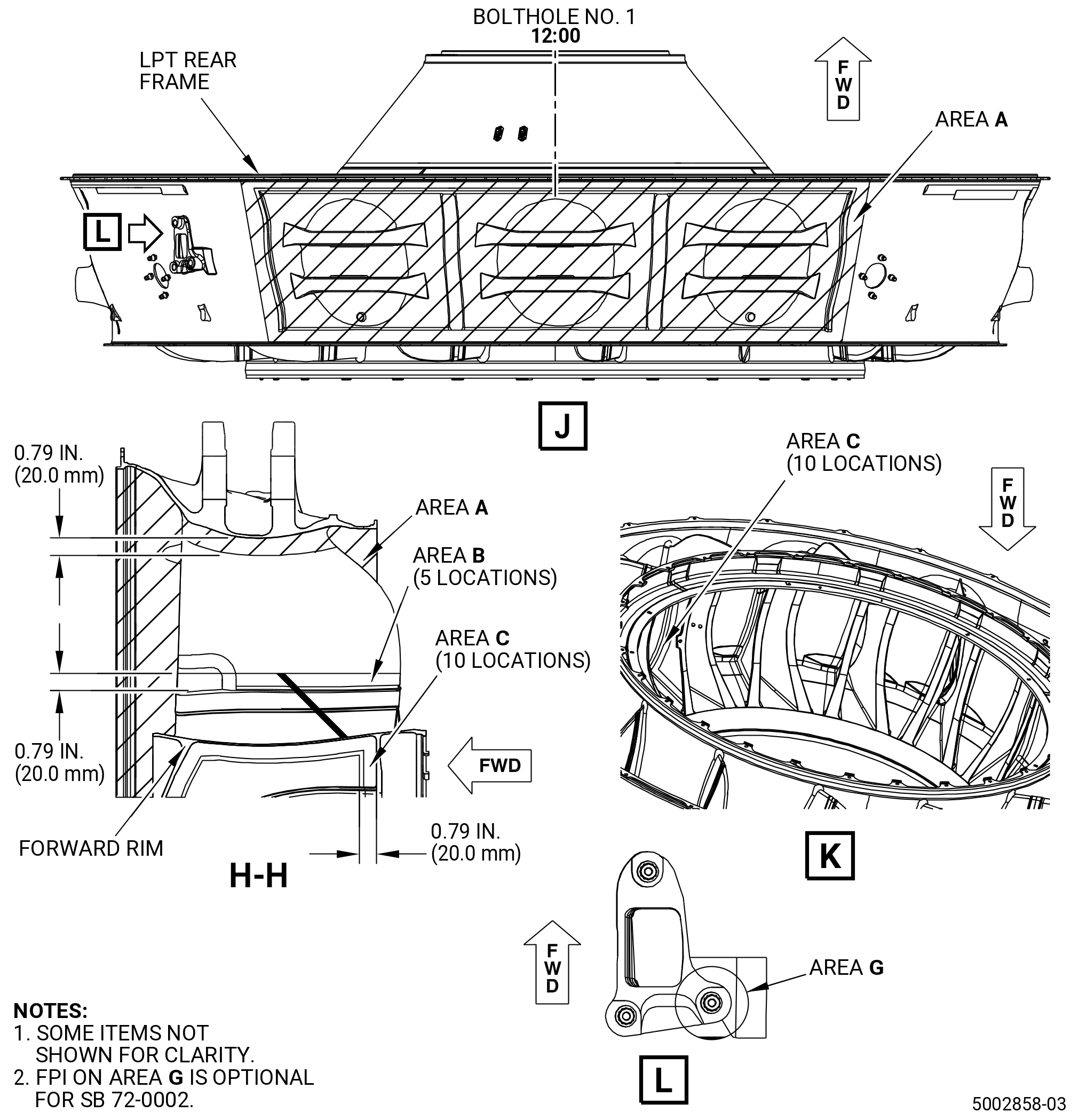
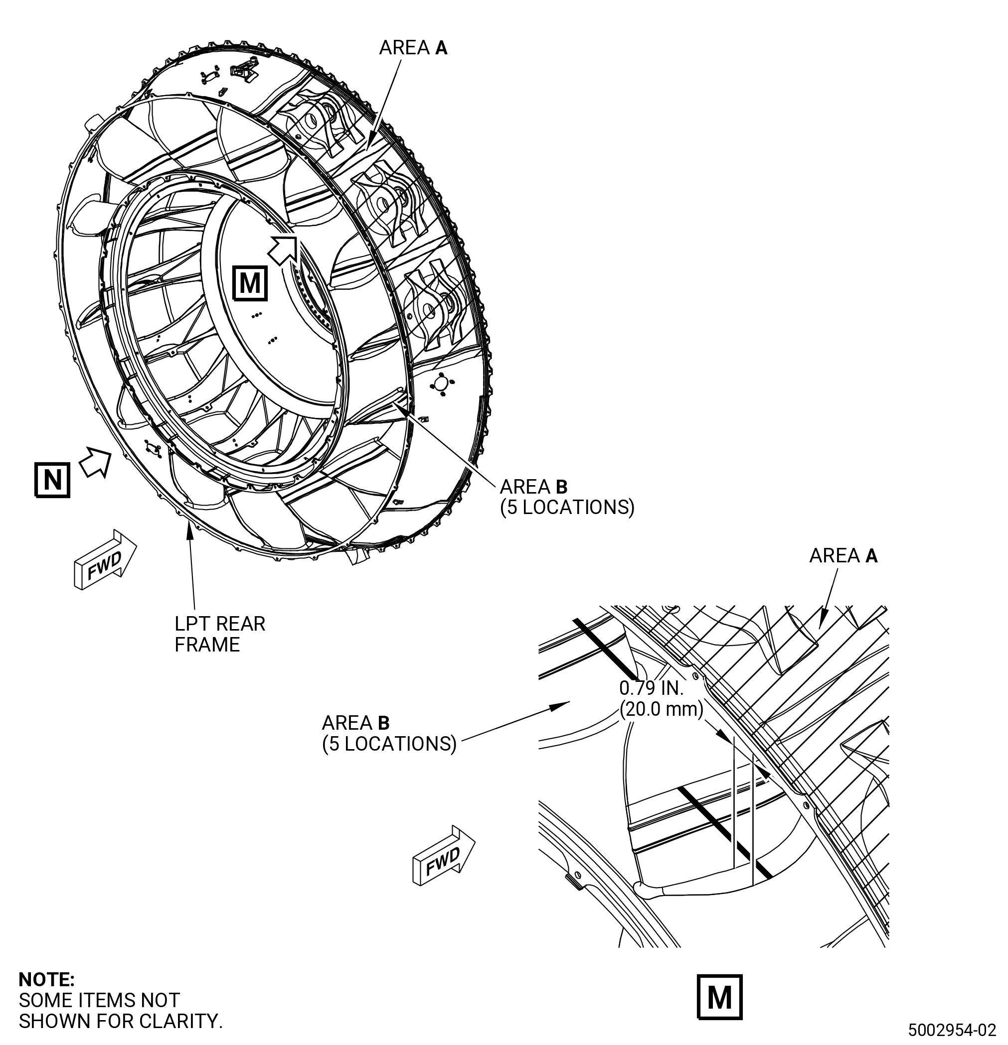
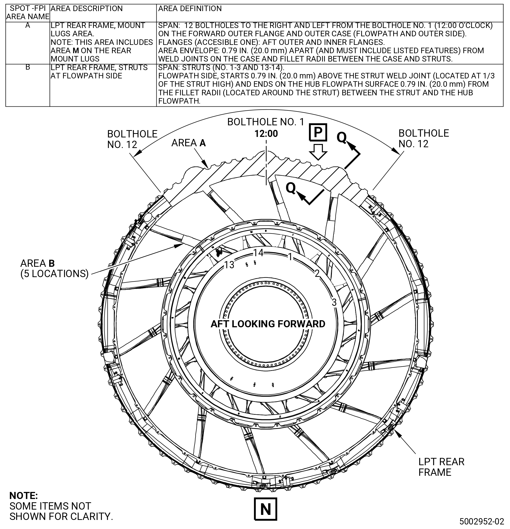
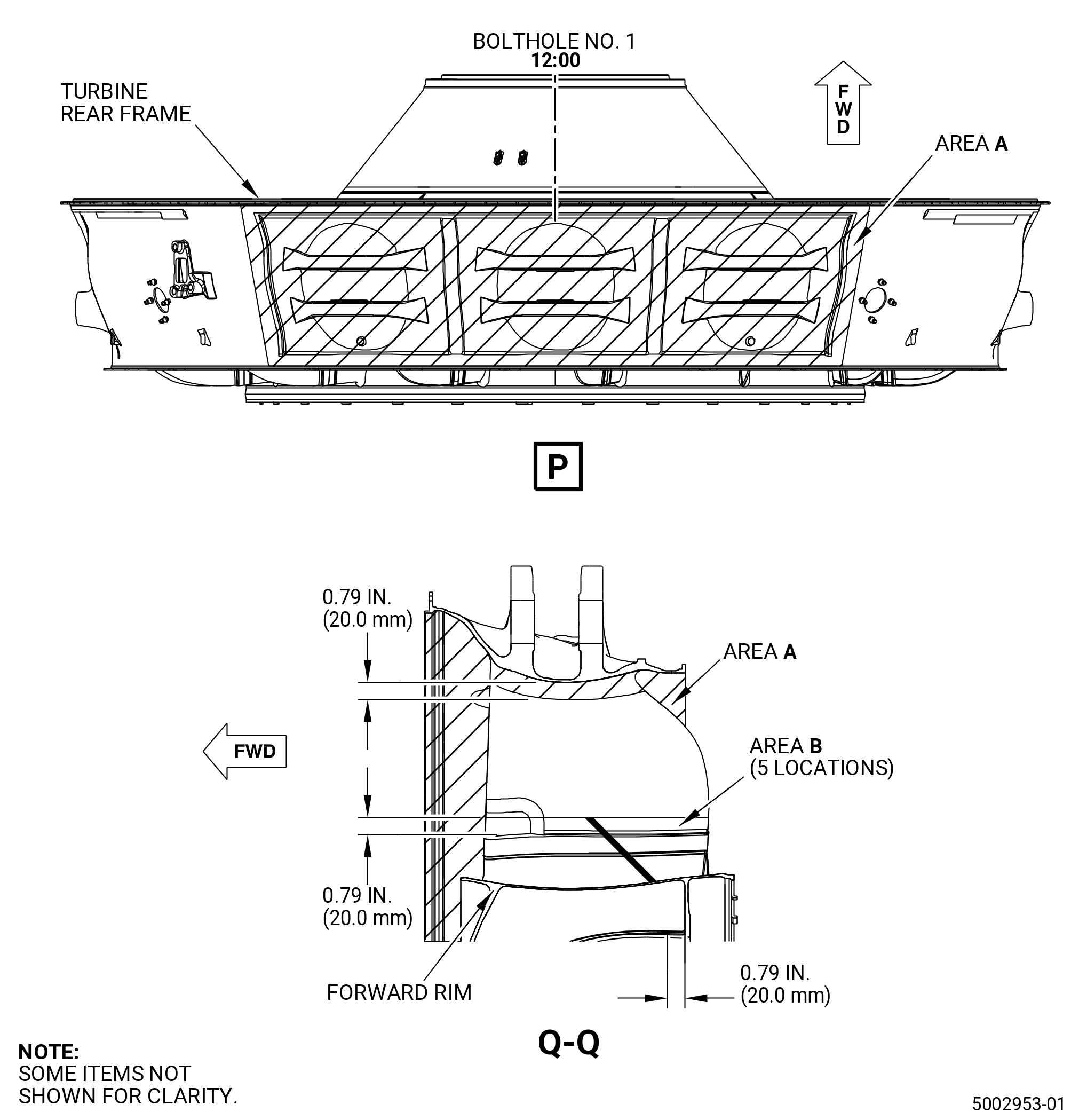
| (1) | Do a Class C spot-fluorescent-penetrant inspection of the outer and inner surfaces of the LPT rear frame. Refer to Figure 803 with spot-fluorescent-penetrant inspection areas definition and TASK 70-32-03-230-002 (SPOT-FLUORESCENT-PENETRANT INSPECTION). The limits must meet Class A (non welded parts) for structures and flanges and Class B (fusion welded parts) for welds. Refer to TASK 70-31-02-220-003 (ACCEPTABILITY LIMITS FOR FLUORESCENT PENETRANT INSPECTION). |
| (a) | Indications less than 0.03 inch (0.8 mm) are not interpretable and are acceptable. |
| * * * END PRE SB 72-0160 |
| * * * END PRE SB 72-0138 |
| * * * END PRE SB 72-0063 |
| Subtask 72-00-04-230-003 |
| * * * SB 72-0063 |
| * * * SB 72-0138 |
| * * * SB 72-0160 |
| (1).A. | Do a Class C spot-fluorescent-penetrant inspection of the outer and inner surfaces of the LPT rear frame. Refer to Figure 804 and TASK 70-32-03-230-002 (SPOT-FLUORESCENT-PENETRANT INSPECTION). The limits must meet Class A (non welded parts) for structures and flanges and Class B (fusion welded parts) for welds. Refer to TASK 70-31-02-220-003 (ACCEPTABILITY LIMITS FOR FLUORESCENT PENETRANT INSPECTION). |
| (a) | Indications less than 0.03 inch (0.8 mm) are not interpretable and are acceptable. |
| * * * END SB 72-0160 |
| * * * END SB 72-0138 |
| * * * END SB 72-0063 |
| 4 . | Visual Inspection. |
| Subtask 72-00-04-220-001 |
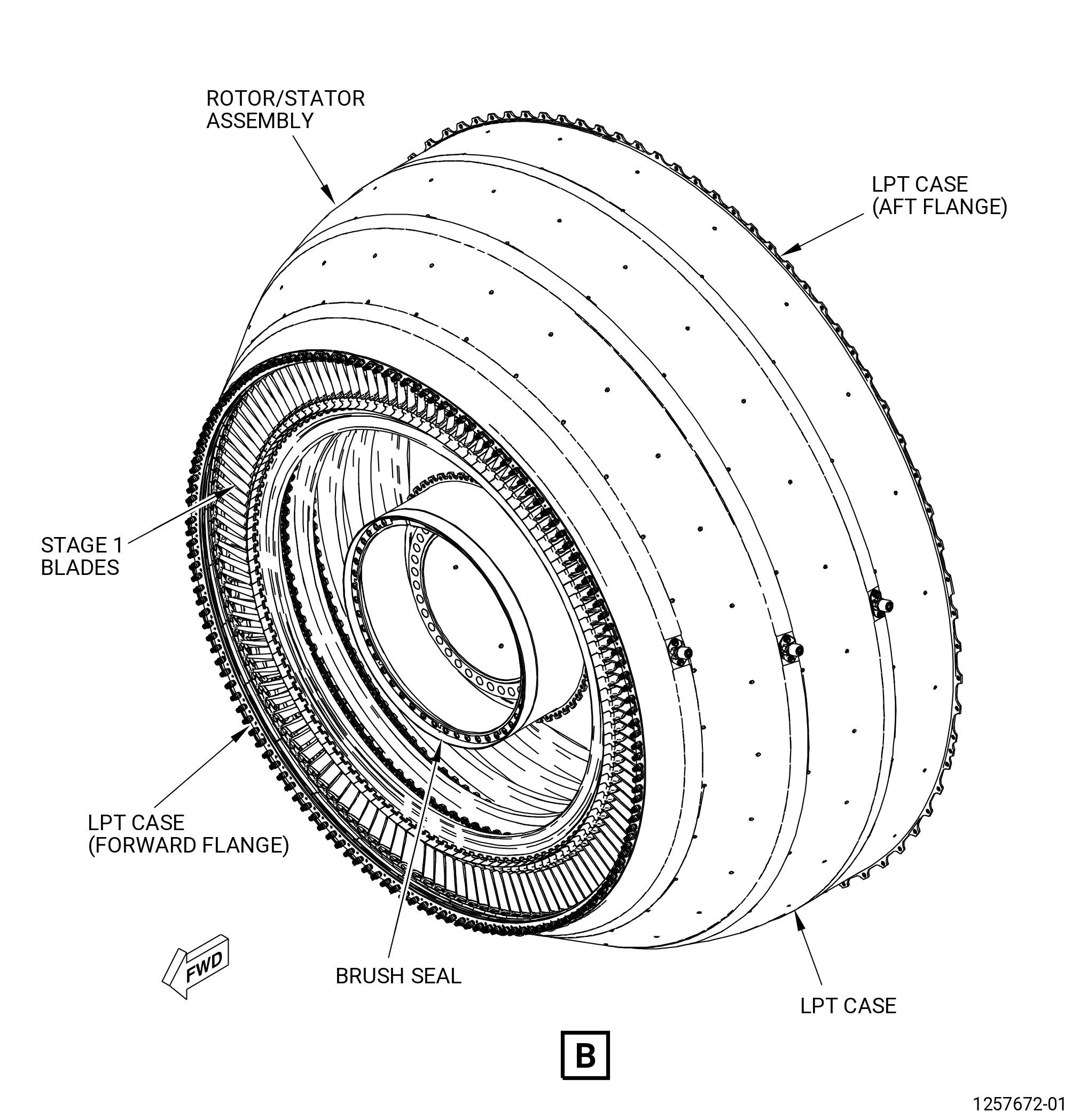
| A. | Do an inspection of the forward flange of the low pressure turbine case (LPT case) (935C1) as follows. Refer to Figure 802. |
| (1) | Cracks: |
| Maximum serviceable limit: |
|
| Repair method: |
|
| Subtask 72-00-04-220-037 |
| (2) | Nicks, scores, and scratches: |
| Maximum serviceable limit: |
|
| Repair method: |
|
| Subtask 72-00-04-220-038 |
| (3) | Dents: |
| Maximum serviceable limit: |
|
| Repair method: |
|
| Subtask 72-00-04-220-003 |
| B. | Do an inspection of the aft flange of the LPT case (935C1) as follows. Refer to Figure 802. |
| (1) | Cracks: |
| Maximum serviceable limit: |
|
| Repair method: |
|
| Subtask 72-00-04-220-041 |
| (2) | Nicks, scores, and scratches: |
| Maximum serviceable limit: |
|
| Repair method: |
|
| Subtask 72-00-04-220-042 |
| (3) | Dents: |
| Maximum serviceable limit: |
|
| Repair method: |
|
| Subtask 72-00-04-220-108 |
| C. | Do an inspection of the visible portions of the stage 2, stage 4, and stage 6 borescope ports as follows: |
| (1) | Cracks in the borescope seat: |
| Maximum serviceable limit: |
|
| Repair method: |
|
| Subtask 72-00-04-220-109 |
| (2) | Damage to the borescope plugs: |
| Maximum serviceable limit: |
|
| Repair method: |
|
| Subtask 72-00-04-220-117 |
| (3) | Discoloration of the borescope plugs: |
| Maximum serviceable limit: |
|
| Repair method: |
|
| Subtask 72-00-04-220-110 |
| (4) | Damage to the borescope seat nuts: |
| Maximum serviceable limit: |
|
| Repair method: |
|
| Subtask 72-00-04-220-004 |
| D. | Do an inspection of all other areas of the LPT case (935C1) as follows. Refer to Figure 802. |
| (1) | Cracks: |
| Maximum serviceable limit: |
|
| Repair method: |
|
| Subtask 72-00-04-220-043 |
| (2) | Nicks: |
| Maximum serviceable limit: |
|
| Repair method: |
|
| Subtask 72-00-04-220-044 |
| (3) | Scratches and scores: |
| Maximum serviceable limit: |
|
| • |
|
| • |
|
| Repair method: |
|
| Subtask 72-00-04-220-045 |
| (4) | Dents: |
| Maximum serviceable limit: |
|
| Repair method: |
|
| Subtask 72-00-04-220-046 |
| (5) | Hot spots (distortion): |
| Maximum serviceable limit: |
|
| Repair method: |
|
| Subtask 72-00-04-220-047 |
| (6) | Heat discoloration: |
| Maximum serviceable limit: |
|
| Repair method: |
|
| Subtask 72-00-04-220-048 |
| (7) | Bulges: |
| Maximum serviceable limit: |
|
| Repair method: |
|
| Subtask 72-00-04-220-005 |
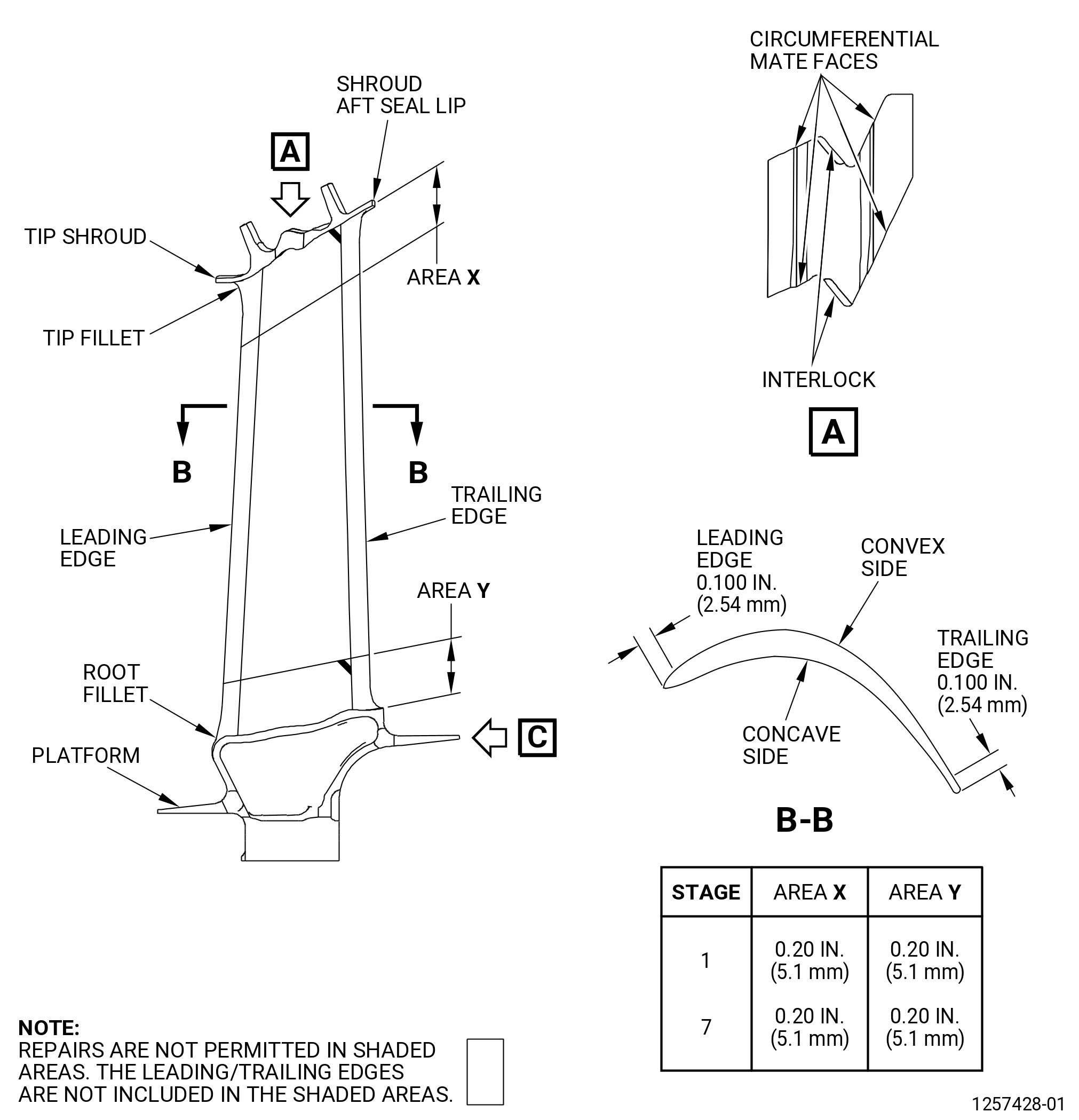
| E. | Do an inspection of all areas of the stage 1 LPT blades (stage 1 blades) (930A1) and the stage 7 LPT blades (stage 7 blades) (930A7) as follows. Refer to Figure 805. |
| (1) | Cracks: |
| Maximum serviceable limit: |
|
| Repair method: |
|
| Subtask 72-00-04-220-151 |
| (2) | Stage 1 blades for corrosion on the airfoil and the tip and root fillets: |
| Maximum serviceable limit: |
|
| Maximum repairable limit: |
|
| Repair method: |
|
| Subtask 72-00-04-220-152 |
| (3) | Stage 1 blades for corrosion on the platform: |
| Maximum serviceable limit: |
|
| Maximum repairable limit: |
|
| Repair method: |
|
| Subtask 72-00-04-220-049 |
| (4) | Stage 7 blades for corrosion: |
| Maximum serviceable limit: |
|
| Repair method: |
|
| Subtask 72-00-04-220-120 |
| F. | Do an inspection of the surfaces of the airfoil of the stage 1 blade. |
| (1) | Metal splatter: |
| Maximum serviceable limit: |
|
| Repair method: |
|
| Subtask 72-00-04-220-006 |
| G. | Do an inspection of areas X and Y on the surfaces of the concave and convex sides of the stage 1 (930A1) and stage 7 blades (930A7) as follows. Refer to Figure 805. |
| (1) | Nicks, scores, scratches, and pitting: |
| Maximum serviceable limit: |
|
| Repair method: |
|
| Subtask 72-00-04-220-050 |
| (2) | High Metal: |
| Maximum serviceable limit: |
|
| Maximum repairable limit: |
|
| Repair method: |
|
| Subtask 72-00-04-220-051 |
| (3) | Dents: |
| Maximum serviceable limit: |
|
| Repair method: |
|
| Subtask 72-00-04-220-007 |
| H. | Do an inspection of the surfaces of the concave and convex sides of the stage 1 blades (930A1), but do not include areas X and Y, as follows. Refer to Figure 805. |
| (1) | Nicks and scratches: |
| Maximum serviceable limit: |
|
| Maximum repairable limit: |
|
| Repair method: |
|
| Subtask 72-00-04-220-052 |
| (2) | Dents: |
| Maximum serviceable limit: |
|
| Repair method: |
|
| Subtask 72-00-04-220-008 |
| * * * PRE SB 72-0040 |
| I. | Do an inspection of the platforms of the stage 1 (05-010 , 72-56-00) (SIN 930A1) and stage 7 blades (10-190 , 72-56-00) (SIN 930A7) (does not include blade root fillet radiuses, unless specified differently). Refer to Figure 805 and as follows: |
| (1) | Nicks and scratches: |
| Maximum serviceable limit: |
|
| Repair method: |
|
| Subtask 72-00-04-220-053 |
| (2) | Dents: |
| Maximum serviceable limit: |
|
| Repair method: |
|
| * * * END PRE SB 72-0040 |
| Subtask 72-00-04-220-198 |
| * * * SB 72-0040 |
| I.A. | Do an inspection of the platforms of the stage 1 (05A-010 , 72-56-00) (SIN 930A1) and stage 7 blades (10A-190 , 72-56-00) (SIN 930A7) (does not include blade root fillet radiuses, unless specified differently). Refer to Figure 805 and as follows: |
| (1) | Nicks, chips, and scratches on stage 1 blade: |
| Maximum serviceable limit: |
|
| Repair method: |
|
| Subtask 72-00-04-220-199 |
| (2) | Nicks, chips, and scratches on stage 7 blade: |
| Maximum serviceable limit: |
|
| Repair method: |
|
| Subtask 72-00-04-220-200 |
| (3) | Dents: |
| Maximum serviceable limit: |
|
| Repair method: |
|
| * * * END SB 72-0040 |
| Subtask 72-00-04-220-009 |
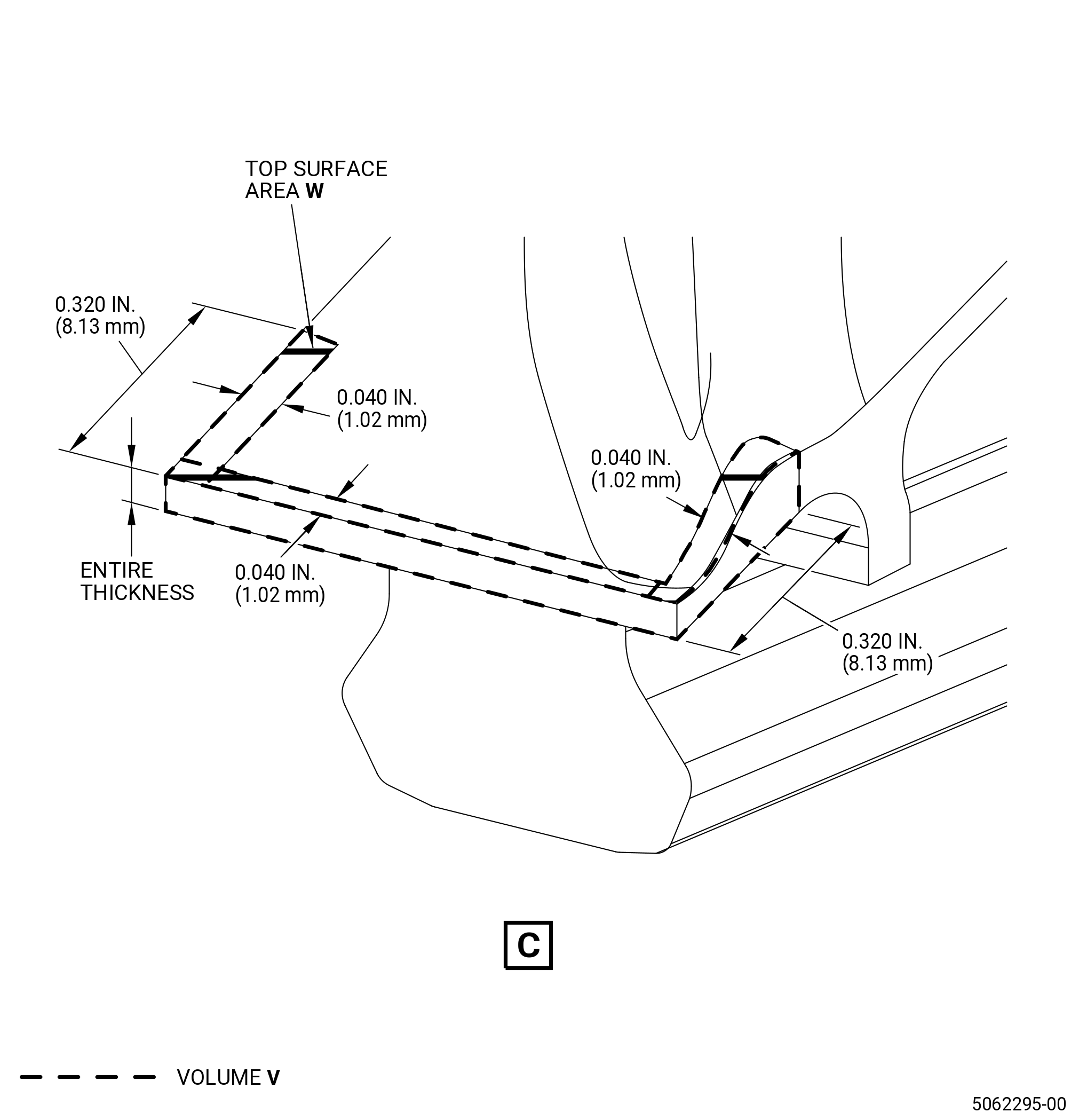
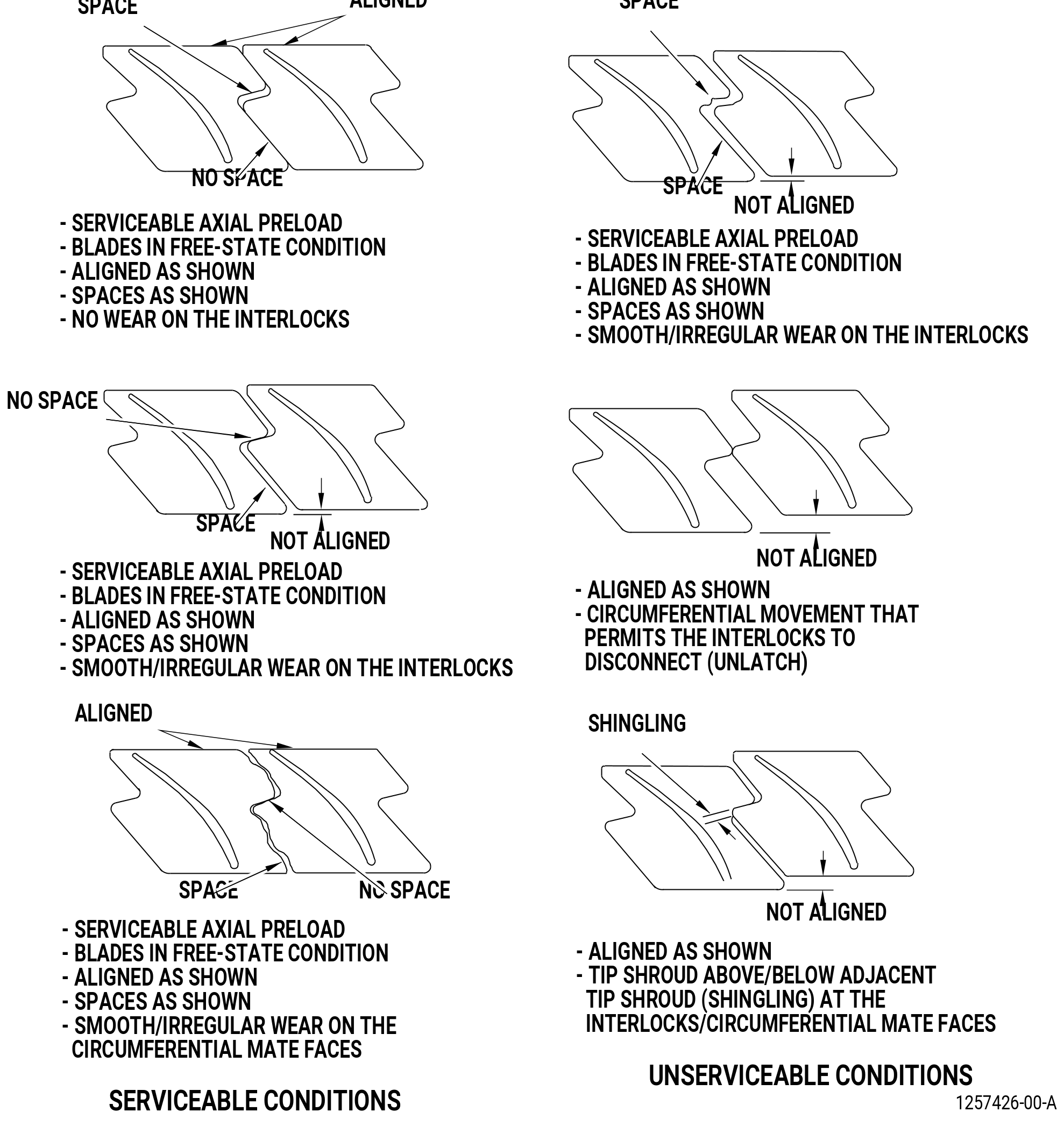
| J. | Do an inspection of the tip shroud of the stage 1 (930A1) and stage 7 blades (930A7) as follows. Refer to Figure 805. |
| (1) | Nicks and scratches: |
| Maximum serviceable limit: |
|
| Repair method: |
|
| Subtask 72-00-04-220-054 |
| (2) | Dents: |
| Maximum serviceable limit: |
|
| Repair method: |
|
| Subtask 72-00-04-220-055 |
| (3) | Wear on the interlock: |
| Maximum serviceable limit: |
|
| Repair method: |
|
| Subtask 72-00-04-220-056 |
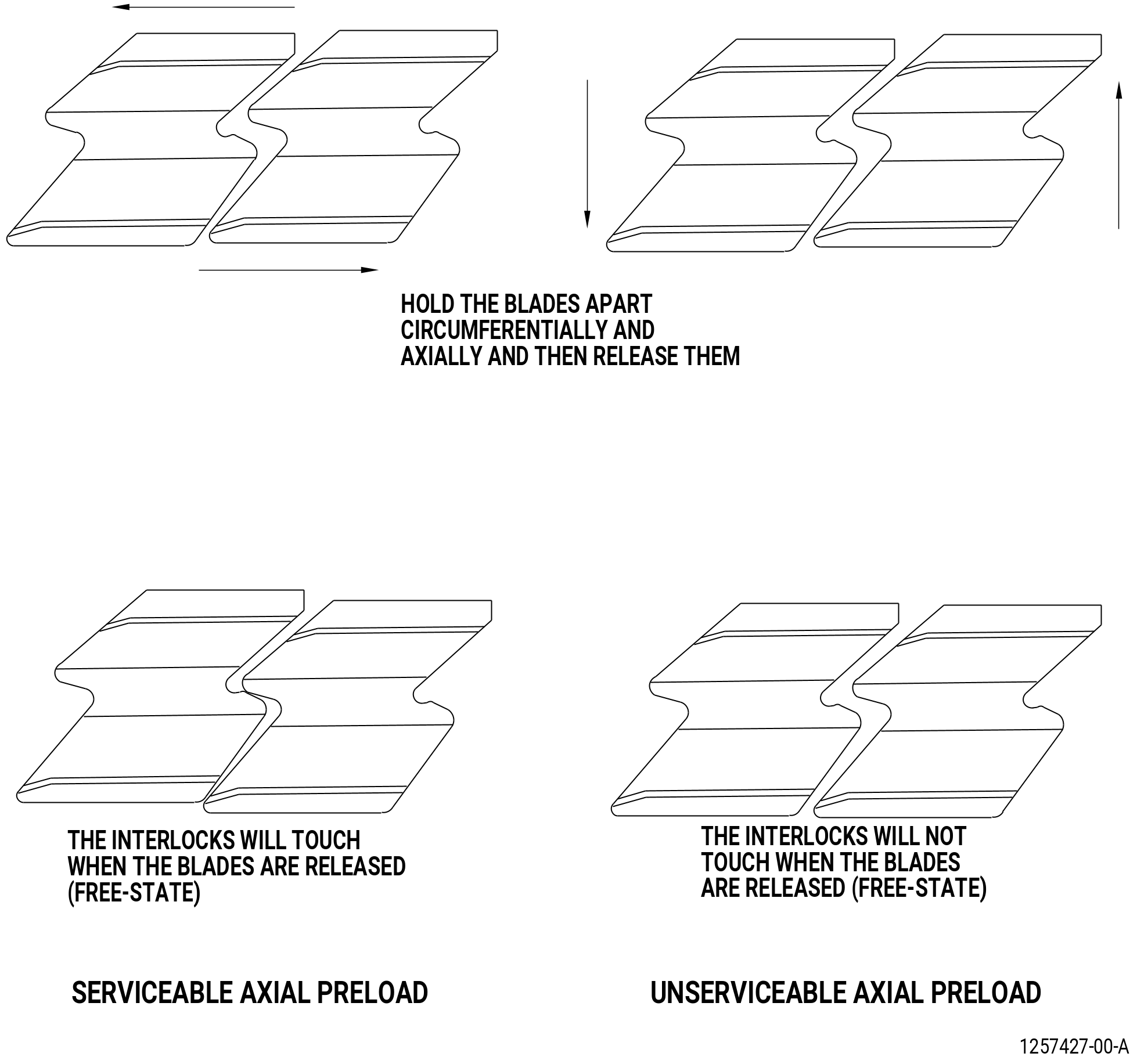
| (4) | Axial preload: |
| Maximum serviceable limit: |
|
| Repair method: |
|
| Subtask 72-00-04-220-057 |
| (5) | Circumferential movement: |
| Maximum serviceable limit: |
|
| Repair method: |
|
| Subtask 72-00-04-220-058 |
| (6) | Shingling or disconnected tip shrouds. Refer to Figure 806. |
| Maximum serviceable limit: |
|
| Maximum repairable limit: |
|
| Repair method: |
|
| Subtask 72-00-04-220-059 |
| (7) | Radial mismatch: |
| Maximum serviceable limit: |
|
| Repair method: |
|
| Subtask 72-00-04-220-060 |
| (8) | Nicks, dents, scores, and pitting on the trailing edge of the tip shroud (stage 7 only): |
| Maximum serviceable limit: |
|
| Maximum repairable limit: |
|
| Repair method: |
|
| Subtask 72-00-04-220-061 |
| (9) | Nicks, scratches, scores, and pitting on the leading edge of the stage 1 blades and the trailing edge of the stage 7 blades: |
| Maximum serviceable limit: |
|
| Repair method: |
|
| Subtask 72-00-04-220-062 |
| (10) | Nicks, dents, scores, and pitting on the tip and root fillets on the leading and trailing edges: |
| Maximum serviceable limit: |
|
| Repair method: |
|
| Subtask 72-00-04-220-063 |
| (11) | Corrosion: |
| Maximum serviceable limit: |
|
| Repair method: |
|
| Subtask 72-00-04-220-010 |
| K. | Do an inspection of areas X and Y on the leading edge of the stage 1 blades (930A1) as follows. Refer to Figure 805. |
| (1) | Nicks, scores, scratches, and pitting: |
| Maximum serviceable limit: |
|
| Repair method: |
|
| Subtask 72-00-04-220-064 |
| (2) | High metal: |
| Maximum serviceable limit: |
|
| Maximum repairable limit: |
|
| Repair method: |
|
| Subtask 72-00-04-220-153 |
| (3) | Dents: |
| Maximum serviceable limit: |
|
| Repair method: |
|
| Subtask 72-00-04-220-011 |
| L. | Do an inspection of the leading edge, but do not include areas X and Y, of the stage 1 blade (930A1) as follows. Refer to Figure 805. |
| (1) | Nicks, scores, scratches, and pitting: |
| Maximum serviceable limit: |
|
| Repair method: |
|
| Subtask 72-00-04-220-065 |
| (2) | High metal: |
| Maximum serviceable limit: |
|
| Maximum repairable limit: |
|
| Repair method: |
|
| Subtask 72-00-04-220-155 |
| (3) | Dents: |
| Maximum serviceable limit: |
|
| • |
|
| • |
|
| Repair method: |
|
| Subtask 72-00-04-220-012 |
| M. | Do an inspection of the tip and root fillets of the stage 1 blade (930A1) as follows. Refer to Figure 805. |
| (1) | Nicks, scores, and pitting on the tip and root fillets: |
| Maximum serviceable limit: |
|
| Repair method: |
|
| Subtask 72-00-04-220-154 |
| (2) | Dents: |
| Maximum serviceable limit: |
|
| Repair method: |
|
| Subtask 72-00-04-220-014 |
| N. | Do an inspection of the LPT rotating air brush seal (brush seal) (930D4) as follows. Refer to Figure 802. |
| (1) | Cracks: |
| Maximum serviceable limit: |
|
| Repair method: |
|
| Subtask 72-00-04-220-066 |
| (2) | Rubs and grooves in the chromium carbide surface: |
| Maximum serviceable limit: |
|
| Repair method: |
|
| Subtask 72-00-04-220-067 |
| (3) | Nicks, dents, and gouges in the chromium carbide surface: |
| Maximum serviceable limit: |
|
| Repair method: |
|
| Subtask 72-00-04-220-111 |
| (4) | Nicks, dents, and scratches in all other locations: |
| Maximum serviceable limit: |
|
| Repair method: |
|
| Subtask 72-00-04-220-112 |
| (5) | Chipped or missing coating: |
| Maximum serviceable limit: |
|
| Repair method: |
|
| Subtask 72-00-04-220-015 |
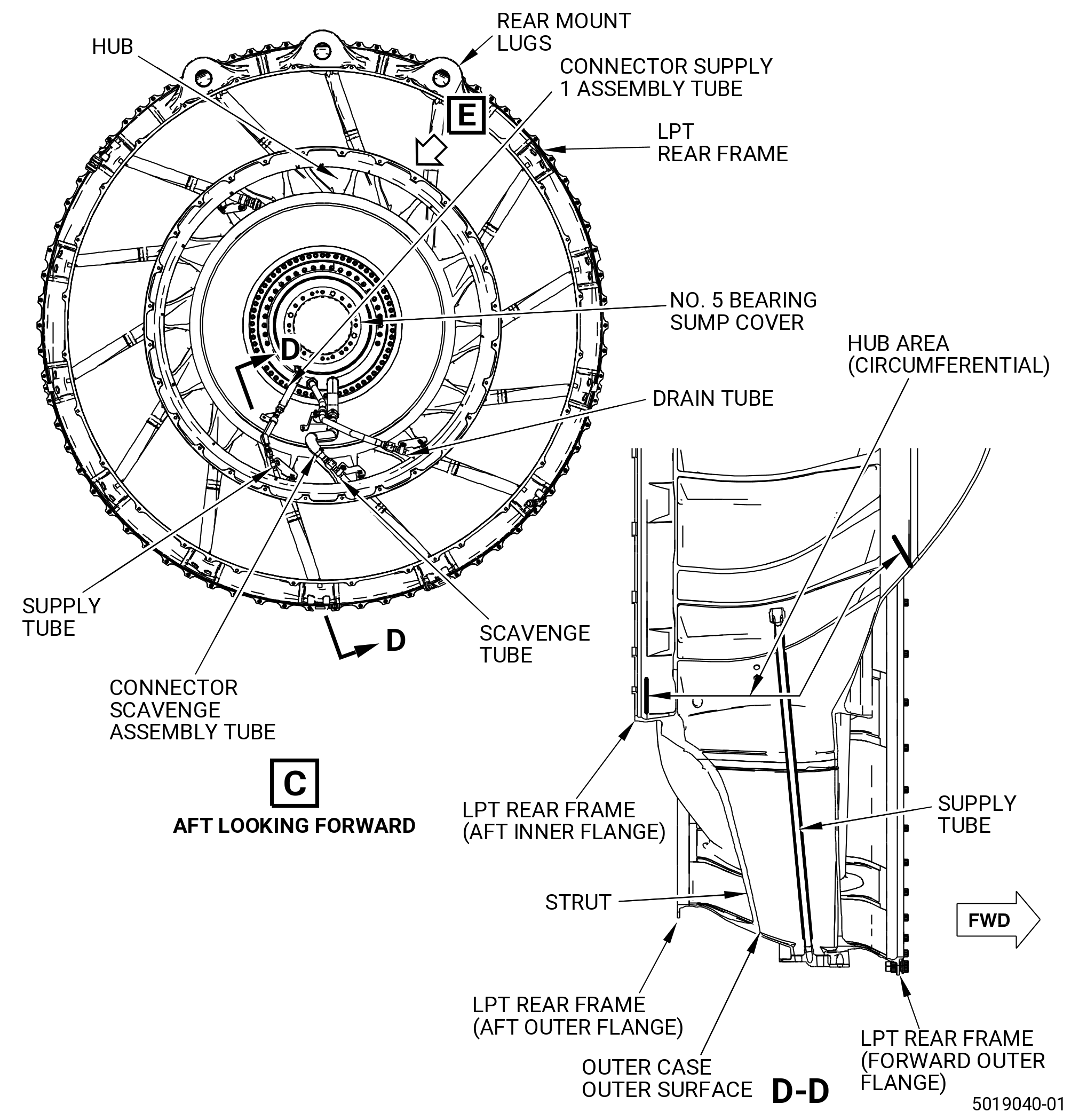
| O. | Do an inspection of the LPT rear frame (01-020) (SIN 94000) forward outer flange. Refer to Figure 802 and do as follows: |
| (1) | Cracks: |
| Maximum serviceable limit: |
|
| Repair method: |
|
| Subtask 72-00-04-220-068 |
| (2) | Nicks, scores, and scratches: |
| Maximum serviceable limit: |
|
| Repair method: |
|
| Subtask 72-00-04-220-069 |
| (3) | Dents: |
| Maximum serviceable limit: |
|
| Repair method: |
|
| Subtask 72-00-04-220-016 |
| P. | Do an inspection of the outer case outer surface, excluding area A (rear mount lugs) of the LPT rear frame (01-020) (SIN 94000). Refer to Figure 802 and do as follows: |
| (1) | Cracks in the parent material: |
| Maximum serviceable limit: |
|
| Repair method: |
|
| Subtask 72-00-04-220-133 |
| (2) | Cracks in the welds: |
| Maximum serviceable limit: |
|
| Repair method: |
|
| Subtask 72-00-04-220-070 |
| (3) | Nicks, scores, and scratches: |
| Maximum serviceable limit: |
|
| Repair method: |
|
| Subtask 72-00-04-220-071 |
| (4) | Dents: |
| Maximum serviceable limit: |
|
| Repair method: |
|
| Subtask 72-00-04-220-125 |
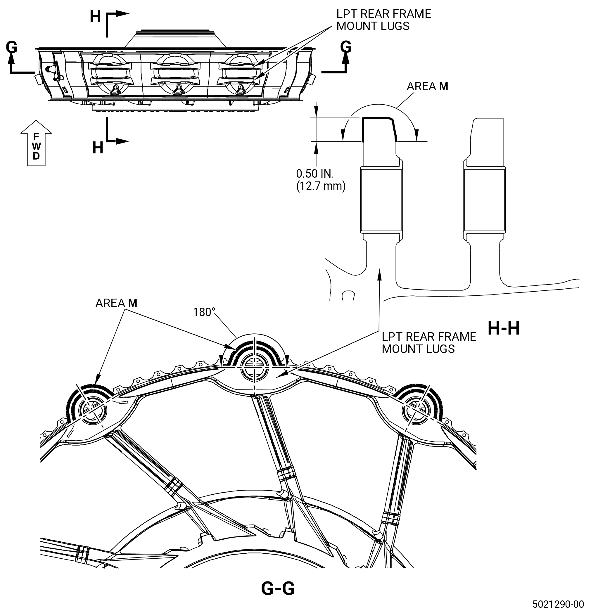
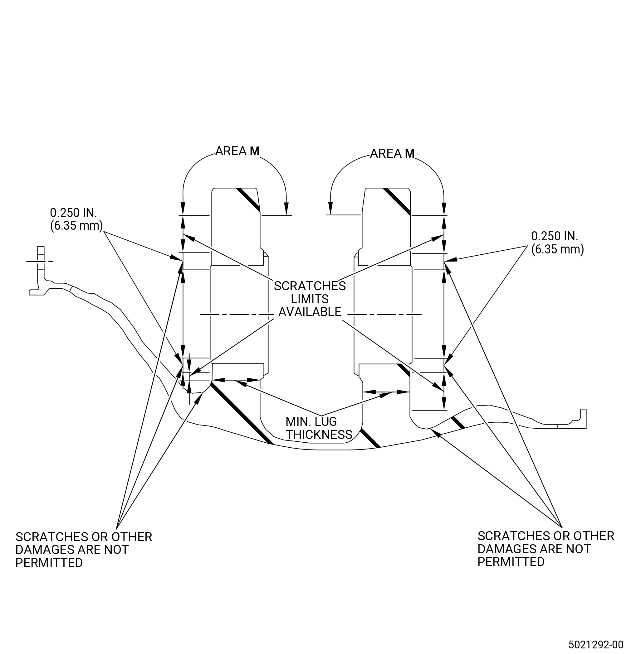
| Q. | Do an inspection of the rear mount lugs area given by area A (airflow side and outer case outer surface). Refer to Figure 802 and Figure 808 and do as follows: |
| (1) | Cracks in parent metal: |
| Maximum serviceable limit: |
|
| Repair method: |
|
| Subtask 72-00-04-220-128 |
| (2) | Cracks in the welds: |
| Maximum serviceable limit: |
|
| Repair method: |
|
| Subtask 72-00-04-220-134 |
| (3) | Bushing that is out of position: |
| Maximum serviceable limit: |
|
| Repair method: |
|
| Subtask 72-00-04-220-135 |
| (4) | Bushing that is missing: |
| Maximum serviceable limit: |
|
| Repair method: |
|
| Subtask 72-00-04-220-136 |
| (5) | Nicks, dents, scores, and scratches (area M not included): |
| Maximum serviceable limit: |
|
| Repair method: |
|
| Subtask 72-00-04-220-137 |
| (6) | Nicks, dents, scores, and scratches in area M: |
| Maximum serviceable limit: |
|
| Maximum repairable limit: |
|
| Repair method: |
|
| Subtask 72-00-04-220-138 |
| NOTE: |
|
| (7) | Circumferential scratches or scores on the forward surface of the forward lugs around mount bushings: |
| Maximum serviceable limit: |
|
| Maximum repairable limit: |
|
| Repair method: |
|
| Subtask 72-00-04-220-139 |
| (8) | Circumferential scratches or scores on the aft surface of the aft lugs around mount bushings: |
| Maximum serviceable limit: |
|
| Maximum repairable limit: |
|
| Repair method: |
|
| Subtask 72-00-04-220-017 |
| R. | Do an inspection of the aft outer flange of the LPT rear frame (01-020) (SIN 94000). Refer to Figure 802 and as follows: |
| (1) | Cracks: |
| Maximum serviceable limit: |
|
| Repair method: |
|
| Subtask 72-00-04-220-072 |
| (2) | Nicks, scores, and scratches: |
| Maximum serviceable limit: |
|
| Repair method: |
|
| Subtask 72-00-04-220-073 |
| (3) | Dents: |
| Maximum serviceable limit: |
|
| Repair method: |
|
| Subtask 72-00-04-220-121 |
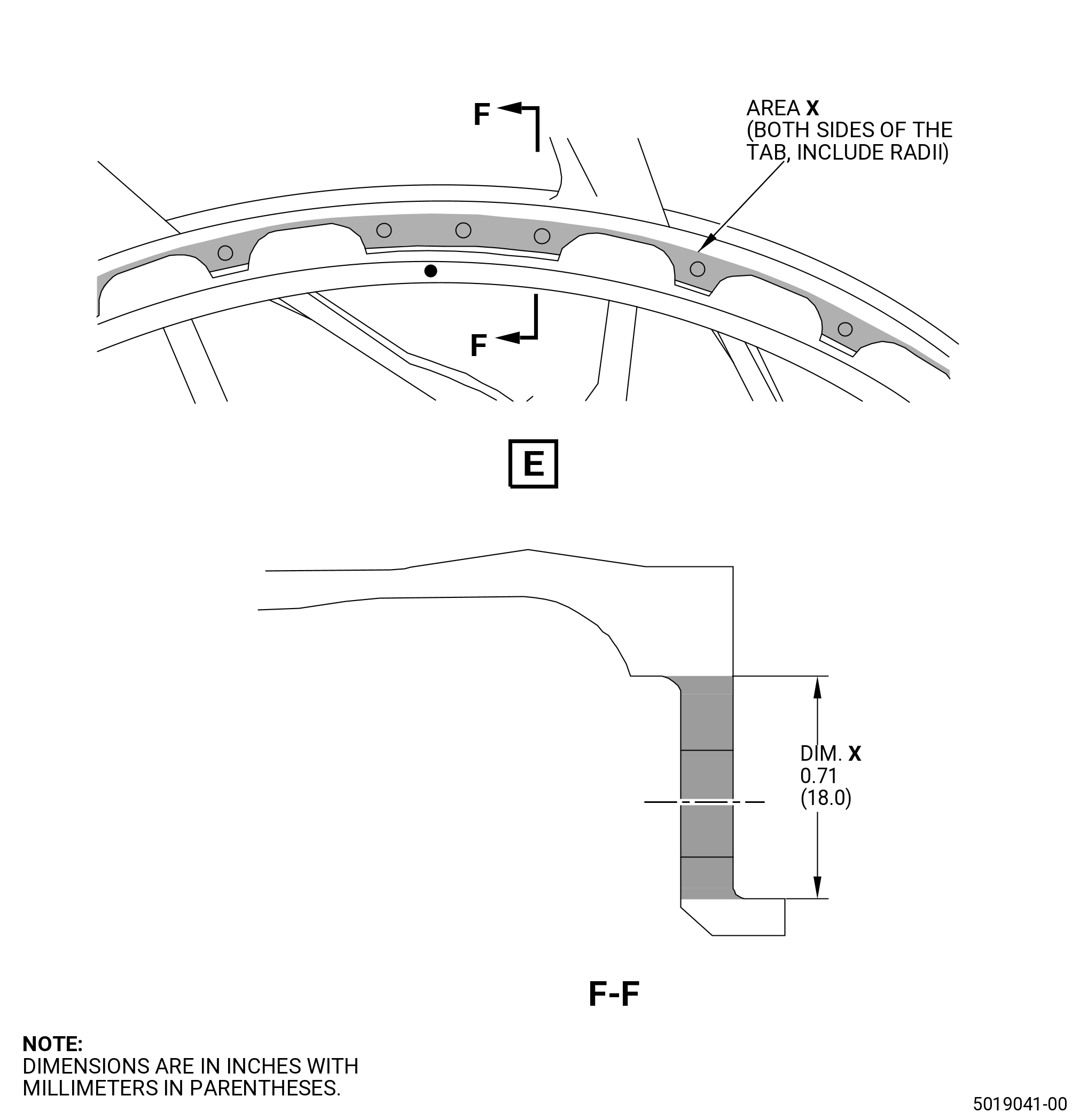
| S. | Do an inspection of the aft inner flange of the LPT rear frame. Refer to Figure 802 and do as follows: |
| (1) | Cracks: |
| Maximum serviceable limit: |
|
| Repair method: |
|
| Subtask 72-00-04-220-122 |
| (2) | Nicks, dents, scores, and scratches (area X not included): |
| Maximum serviceable limit: |
|
| Maximum repairable limit: |
|
| Repair method: |
|
| Repair method: |
|
| Subtask 72-00-04-220-123 |
| (3) | Nicks, dents, scores, and scratches at area X: |
| Maximum serviceable limit: |
|
| Repair method: |
|
| Subtask 72-00-04-220-124 |
| (4) | Deformation: |
| Maximum serviceable limit: |
|
| Repair method: |
|
| Subtask 72-00-04-220-018 |
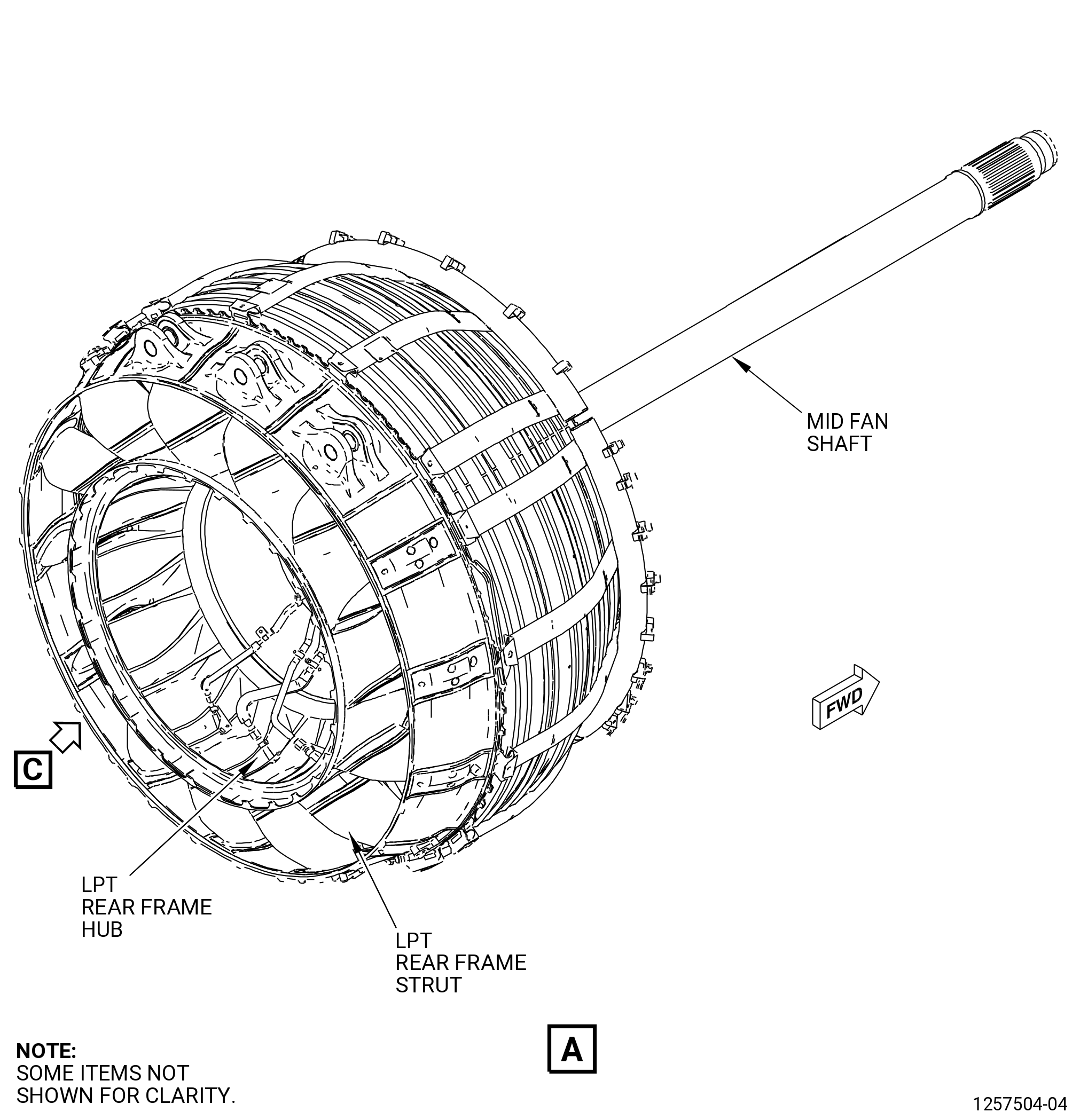
| T. | Do an inspection of the struts and airflow surfaces (hub airflow surface and outer case airflow surface), excluding area A (rear mount lugs) of the LPT rear frame (01-020) (SIN 94000). Refer to Figure 802 and do as follows: |
| (1) | Cracks: |
| Maximum serviceable limit: |
|
| Repair method: |
|
| Subtask 72-00-04-220-074 |
| (2) | Nicks, scores, and scratches: |
| Maximum serviceable limit: |
|
| Repair method: |
|
| Subtask 72-00-04-220-075 |
| (3) | Dents on struts (struts No. 7 and No. 8 not included): |
| Maximum serviceable limit: |
|
| Repair method: |
|
| Subtask 72-00-04-220-126 |
| (4) | Dents on struts No. 7 and No. 8: |
| Maximum serviceable limit: |
|
| Repair method: |
|
| Subtask 72-00-04-220-127 |
| (5) | Dents on airflow surfaces (hub airflow surface and outer case airflow surface): |
| Maximum serviceable limit: |
|
| Repair method: |
|
| Subtask 72-00-04-220-019 |
| U. | Do an inspection of the hub area of the LPT rear frame (01-020) (SIN 94000). Refer to Figure 802 and do as follows: |
| (1) | Cracks: |
| Maximum serviceable limit: |
|
| Repair method: |
|
| Subtask 72-00-04-220-076 |
| (2) | Nicks, dents, scores, and scratches: |
| Maximum serviceable limit: |
|
| Repair method: |
|
| Subtask 72-00-04-220-077 |
| (3) | Deleted. |
| Subtask 72-00-04-220-078 |
| (4) | Deleted. |
| Subtask 72-00-04-220-079 |
| (5) | Deleted. |
| Subtask 72-00-04-220-020 |
| V. | Do an inspection of the supply tube (443A1) as follows. Refer to Figure 802. |
| (1) | Cracks: |
| Maximum serviceable limit: |
|
| Repair method: |
|
| Subtask 72-00-04-220-080 |
| (2) | Nicks, scores, and scratches: |
| Maximum serviceable limit: |
|
| Repair method: |
|
| Subtask 72-00-04-220-081 |
| (3) | Dents: |
| Maximum serviceable limit: |
|
| Repair method: |
|
| Subtask 72-00-04-220-145 |
| (4) | External coking: |
| Maximum serviceable limit: |
|
| Repair method: |
|
| Subtask 72-00-04-220-021 |
| W. | Do an inspection of the scavenge tube (452A1) as follows. Refer to Figure 802. |
| (1) | Cracks: |
| Maximum serviceable limit: |
|
| Repair method: |
|
| Subtask 72-00-04-220-082 |
| (2) | Nicks, scores, and scratches: |
| Maximum serviceable limit: |
|
| Repair method: |
|
| Subtask 72-00-04-220-083 |
| (3) | Dents: |
| Maximum serviceable limit: |
|
| Repair method: |
|
| Subtask 72-00-04-220-146 |
| (4) | External coking: |
| Maximum serviceable limit: |
|
| Repair method: |
|
| Subtask 72-00-04-220-118 |
| X. | Do an inspection of the connector supply 1 assembly tube (443A0) and connector scavenge assembly tube (452A0) as follows. Refer to Figure 802. |
| (1) | Nicks, scratches, chafing, or scores in straight section and bends: |
| Maximum serviceable limit: |
|
| Repair method: |
|
| Subtask 72-00-04-220-147 |
| (2) | External coking: |
| Maximum serviceable limit: |
|
| Repair method: |
|
| Subtask 72-00-04-220-023 |
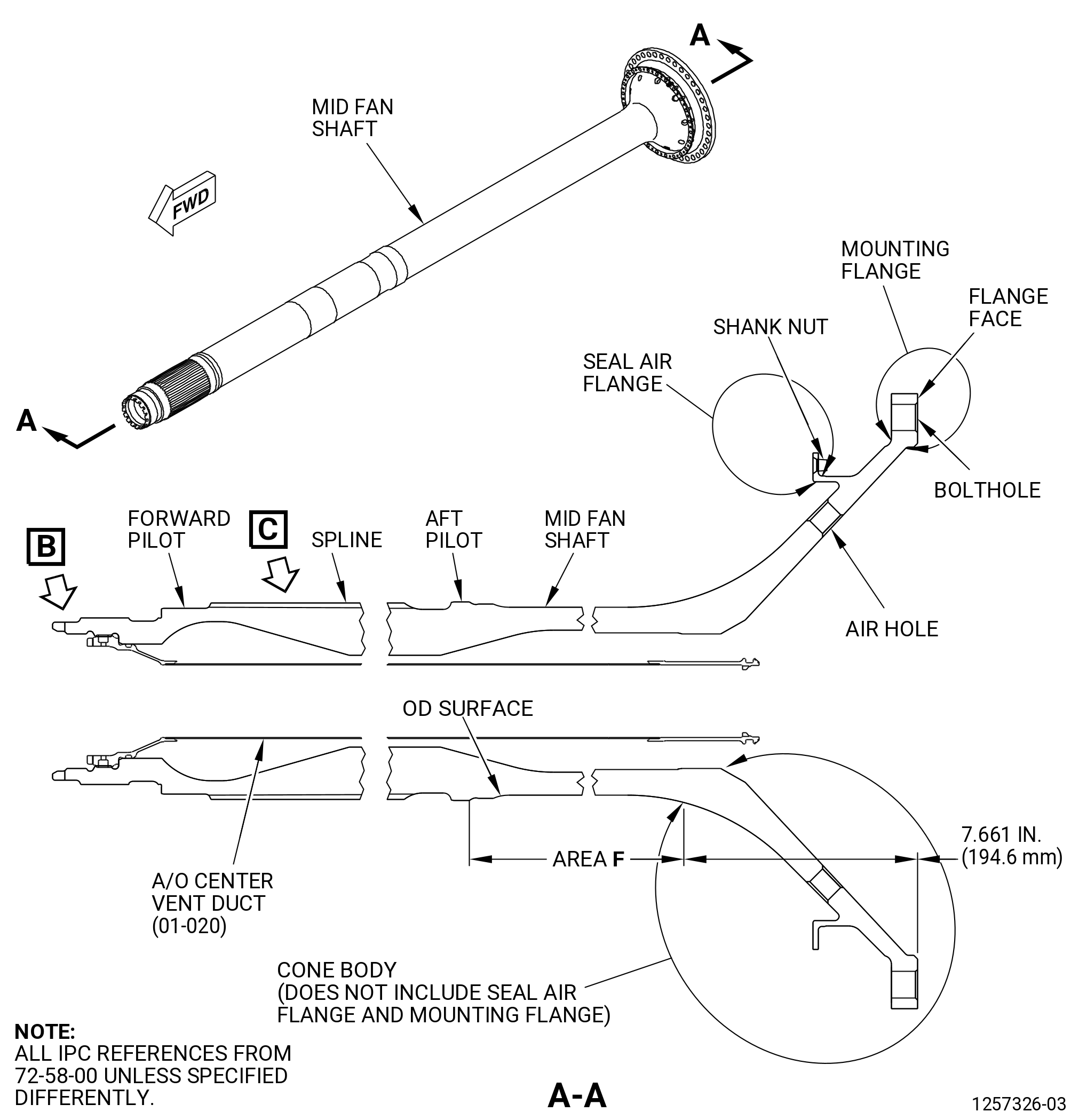
| Y. | Do an inspection of all areas of the mid fan shaft module assembly (mid fan shaft) (81000) as follows. Refer to Figure 809. |
| (1) | Cracks: |
| Maximum serviceable limit: |
|
| Repair method: |
|
| Subtask 72-00-04-220-085 |
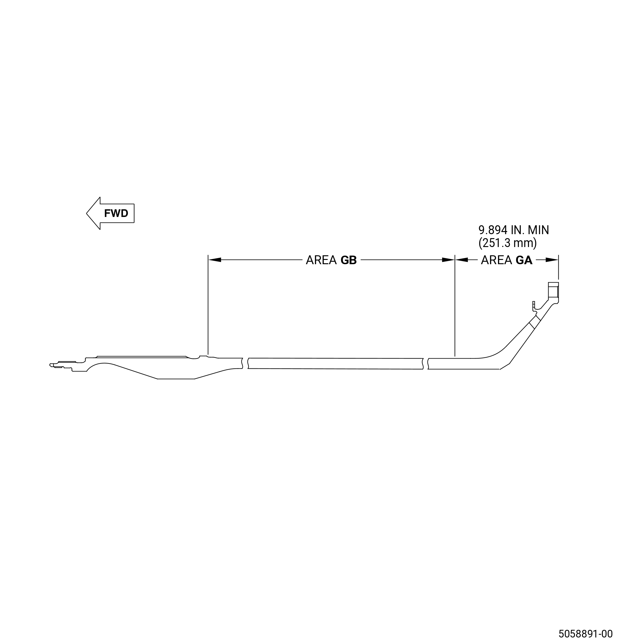
| (2) | Peeling, blistering, and missing aluminum protective coating (this paragraph does not apply to area GA and area GB): |
| Maximum serviceable limit: |
|
| Maximum repairable limit: |
|
| • |
|
| • |
|
| Repair method: |
|
| Subtask 72-00-04-220-086 |
| (3) | Oil and coking deposits: |
| Maximum serviceable limit: |
|
| Maximum repairable limit: |
|
| Repair method: |
|
| Subtask 72-00-04-220-192 |
| (4) | Deleted. |
| Subtask 72-00-04-220-193 |
| (5) | Deleted. |
| Subtask 72-00-04-220-201 |
| (6) | Peeling, blistering, and missing coating (for area GA): |
| NOTE: |
|
| NOTE: |
|
| Maximum serviceable limit: |
|
| Maximum repairable limit 1: |
|
| CAUTION: |
|
| • |
|
| • |
|
| Repair method 1: |
|
| Maximum repairable limit 2: |
|
| • |
|
| • |
|
| Repair method 2: |
|
| Subtask 72-00-04-220-202 |
| (7) | Peeling, blistering, and missing coating (for area GB): |
| NOTE: |
|
| Maximum serviceable limit: |
|
| Maximum repairable limit 1: |
|
| CAUTION: |
|
| • |
|
| • |
|
| Repair method 1: |
|
| Maximum repairable limit 2: |
|
| • |
|
| • |
|
| Repair method 2: |
|
| Subtask 72-00-04-220-194 |
| (8) | Corrosion pit: |
| Maximum serviceable limit: |
|
| Repair method: |
|
| Subtask 72-00-04-220-025 |
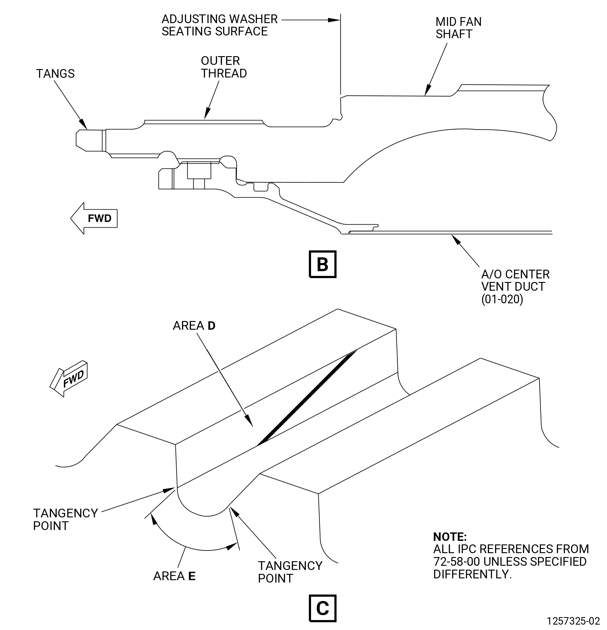
| Z. | Do an inspection of area D (loaded side critical) of the external splines of the mid fan shaft (81000) as follows. Refer to Sheet 2. |
| (1) | Cracks: |
| Maximum serviceable limit: |
|
| Repair method: |
|
| Subtask 72-00-04-220-114 |
| (2) | Nicks and scratches: |
| Maximum serviceable limit: |
|
| Repair method: |
|
| Subtask 72-00-04-220-089 |
| (3) | Fretting: |
| Maximum serviceable limit: |
|
| Repair method: |
|
| Subtask 72-00-04-220-090 |
| (4) | High metal: |
| Maximum serviceable limit: |
|
| Maximum repairable limit: |
|
| Repair method: |
|
| Subtask 72-00-04-220-115 |
| AA. | Do an inspection of area E of the external splines of the mid fan shaft (81000) as follows. Refer to Sheet 2. |
| (1) | Cracks: |
| Maximum serviceable limit: |
|
| Repair method: |
|
| Subtask 72-00-04-220-116 |
| (2) | Nicks and scratches: |
| Maximum serviceable limit: |
|
| Repair method: |
|
| Subtask 72-00-04-220-026 |
| AB. | Do an inspection of the outside diameter (OD) of the external splines of the mid fan shaft (81000) as follows. Refer to Figure 809. |
| (1) | Nicks and scratches: |
| Maximum serviceable limit: |
|
| Repair method: |
|
| Subtask 72-00-04-220-027 |
| AC. | Do an inspection of all other areas of the external splines of the mid fan shaft (81000) as follows. Refer to Figure 809. |
| (1) | Nicks and scratches: |
| Maximum serviceable limit: |
|
| Repair method: |
|
| Subtask 72-00-04-220-092 |
| (2) | Fretting: |
| Maximum serviceable limit: |
|
| Repair method: |
|
| Subtask 72-00-04-220-093 |
| (3) | High metal: |
| Maximum serviceable limit: |
|
| Maximum repairable limit: |
|
| Repair method: |
|
| Subtask 72-00-04-220-028 |
| AD. | Do an inspection of the internal threads and forward threads of the mid fan shaft (81000) as follows. Refer to Figure 809. |
| (1) | Damage: |
| Maximum serviceable limit: |
|
| Maximum repairable limit: |
|
| Repair method: |
|
| Subtask 72-00-04-220-029 |
| AE. | Do an inspection of the torques slots and tangs of the mid fan shaft (81000) as follows. Refer to Figure 809. |
| (1) | Nicks, dents, and burrs in the torque slots and tangs: |
| Maximum serviceable limit: |
|
| Repair method: |
|
| Subtask 72-00-04-220-095 |
| (2) | Bent tangs (handling damage): |
| Maximum serviceable limit: |
|
| Repair method: |
|
| Subtask 72-00-04-220-096 |
| (3) | Cracked tangs: |
| Maximum serviceable limit: |
|
| Repair method: |
|
| Subtask 72-00-04-220-030 |
| AF. | Do an inspection of the forward pilot diameter (diameter B) of the mid fan shaft (81000) as follows. Refer to Figure 809. |
| (1) | Nicks and scratches: |
| Maximum serviceable limit: |
|
| Repair method: |
|
| Subtask 72-00-04-220-097 |
| (2) | Wear/galling: |
| Maximum serviceable limit: |
|
| Repair method: |
|
| Subtask 72-00-04-220-098 |
| (3) | High metal: |
| Maximum serviceable limit: |
|
| Maximum repairable limit: |
|
| Repair method: |
|
| Subtask 72-00-04-220-031 |
| AG. | Do an inspection of the aft pilot diameter (diameter A) of the mid fan shaft (81000) as follows. Refer to Figure 809. |
| (1) | Nicks, dents, and scratches: |
| Maximum serviceable limit: |
|
| Repair method: |
|
| Subtask 72-00-04-220-099 |
| (2) | Wear/galling: |
| Maximum serviceable limit: |
|
| Repair method: |
|
| Subtask 72-00-04-220-100 |
| (3) | High metal: |
| Maximum serviceable limit: |
|
| Maximum repairable limit: |
|
| Repair method: |
|
| Subtask 72-00-04-220-032 |
| AH. | Do an inspection of the adjusting washer seating surface (surface C) of the mid fan shaft (81000) as follows. Refer to Figure 809. |
| (1) | Fretting and galling: |
| Maximum serviceable limit: |
|
| Repair method: |
|
| Subtask 72-00-04-220-101 |
| (2) | Pitting: |
| Maximum serviceable limit: |
|
| Repair method: |
|
| Subtask 72-00-04-220-102 |
| (3) | Nicks and dents: |
| Maximum serviceable limit: |
|
| Repair method: |
|
| Subtask 72-00-04-220-103 |
| (4) | Scratches: |
| Maximum serviceable limit: |
|
| Repair method: |
|
| Subtask 72-00-04-220-104 |
| (5) | High metal: |
| Maximum serviceable limit: |
|
| Maximum repairable limit: |
|
| Repair method: |
|
| Subtask 72-00-04-220-148 |
| AI. | Do an inspection of the OD surface (area F) for: |
| (1) | Cracks: |
| Maximum serviceable limit: |
|
| Repair method: |
|
| Subtask 72-00-04-220-149 |
| (2) | Nicks and dents: |
| Maximum serviceable limit: |
|
| Repair method: |
|
| Subtask 72-00-04-220-150 |
| (3) | Scratches: |
| Maximum serviceable limit: |
|
| Repair method: |
|
| Subtask 72-00-04-220-033 |
| AJ. | Do an inspection of all other areas of the mid fan shaft (81000) as follows. Refer to Figure 809. |
| (1) | Nicks, dents, and scratches: |
| Maximum serviceable limit: |
|
| Repair method: |
|
| Subtask 72-00-04-220-140 |
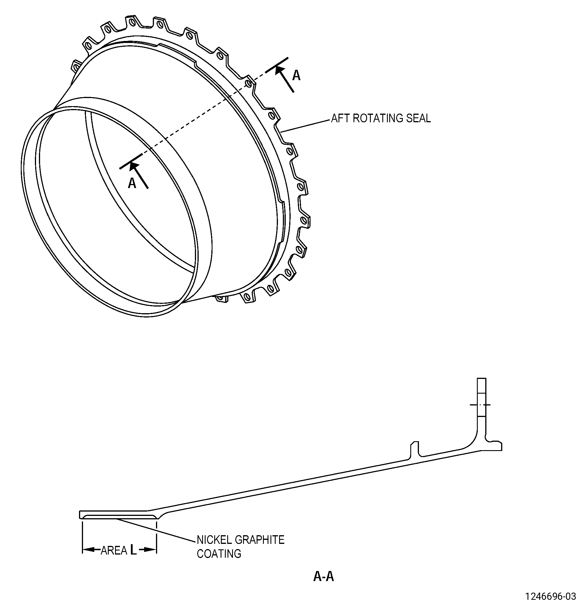
| AK. | Do an inspection of all areas (do not include the coating) of the No. 4 bearing aft rotating seal (aft rotating seal) (35-380 , 72-00-02) (SIN 01406). Refer to Figure 812 and as follows: |
| (1) | Cracks: |
| Maximum serviceable limit: |
|
| Repair method: |
|
| Subtask 72-00-04-220-141 |
| (2) | Nicks, dents, and scratches: |
| Maximum serviceable limit: |
|
| Repair method: |
|
| Subtask 72-00-04-220-142 |
| AL. | Do an inspection of the coating in area L of the aft rotating seal (35-380 , 72-00-02) (SIN 01406). Refer to Figure 812 and as follows: |
| (1) | Rubs or grooves: |
| Maximum serviceable limit: |
|
| Repair method: |
|
| Subtask 72-00-04-220-143 |
| * * * FOR ALL.ALL |
| (2) | Missing coating: |
| Maximum serviceable limit: |
|
| Repair method: |
|
| Subtask 72-00-04-220-144 |
| * * * FOR ALL.ALL |
| (1) | Discoloration: |
| Maximum serviceable limit: |
|
| Repair method: |
|
| Subtask 72-00-04-220-034 |
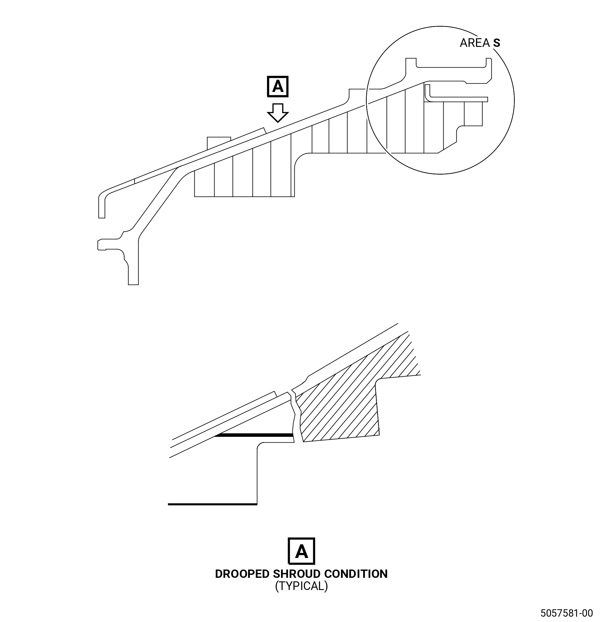
| AM. | Do an inspection of the stage 1 shroud for the features that follow (when visible and if the shroud is still mounted on the LPT case). Refer to Figure 810. |
| (1) | Cracked honeycomb in area S: |
| Maximum serviceable limit: |
|
| Repair method: |
|
| Subtask 72-00-04-220-105 |
| (2) | Deleted. |
| Subtask 72-00-04-220-106 |
| (3) | Drooping/cracking in area A: |
| Maximum serviceable limit: |
|
| Repair method: |
|
| Subtask 72-00-04-220-113 |
| AN. | Do an inspection of the No. 5 bearing sump cover (0150C) as follows. Refer to Figure 802. |
| (1) | External oil coking: |
| Maximum serviceable limit: |
|
| Repair method: |
|
| Subtask 72-00-04-220-174 |
| * * * PRE SB 72-0040 |
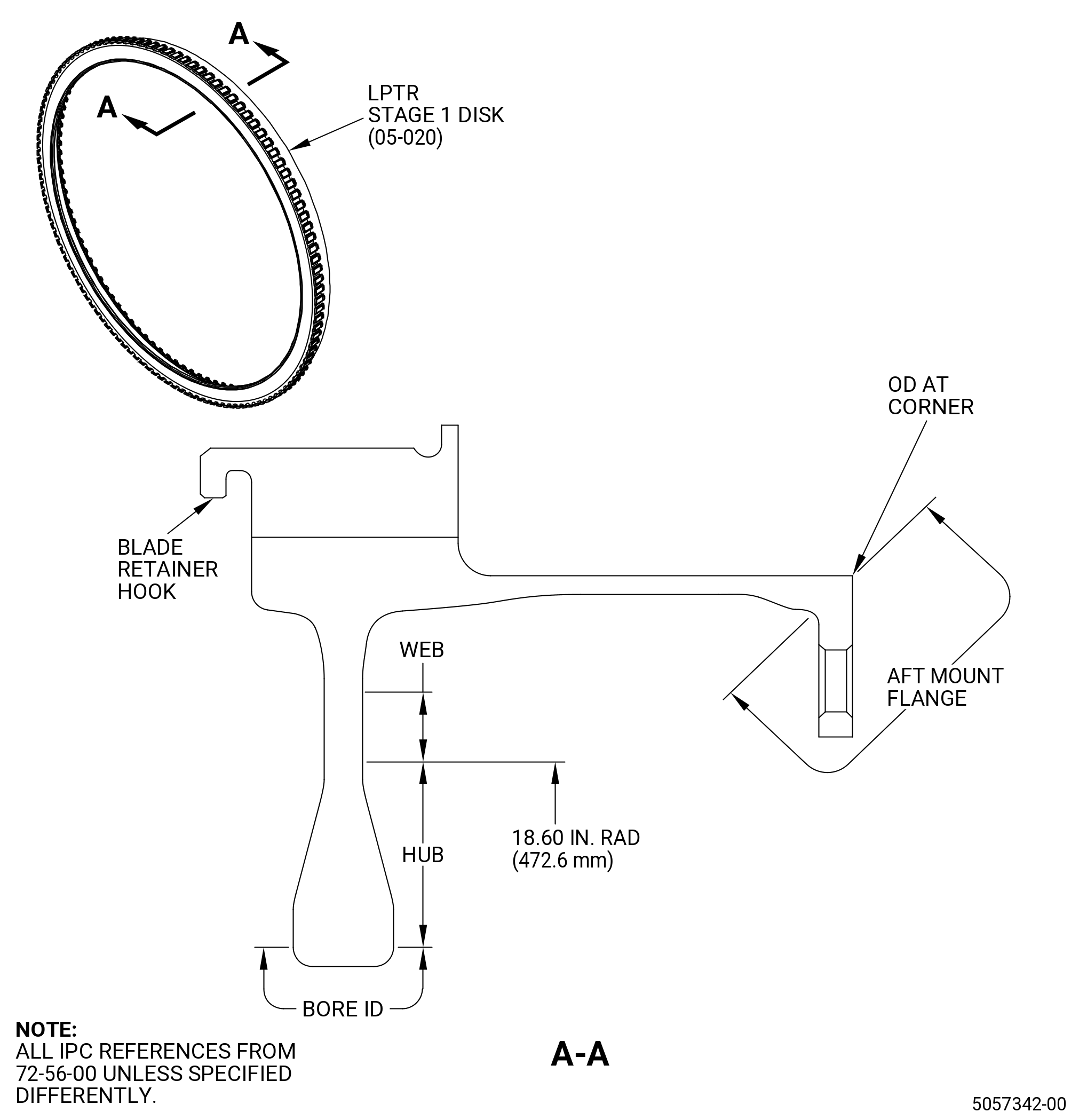
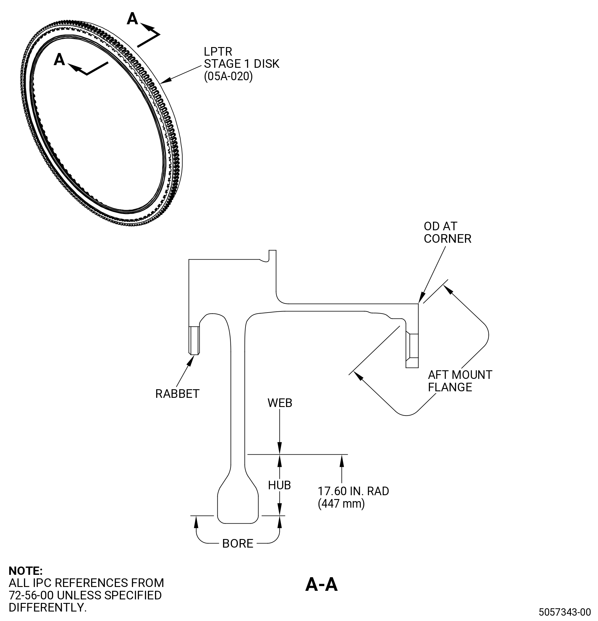
| AO. | Do an inspection of the stage 1 disk other area (does not include dovetail edge) for. Refer to Figure 811. |
| (1) | Cracks: |
| Maximum serviceable limit: |
|
| Repair method: |
|
| Subtask 72-00-04-220-175 |
| (2) | Nicks and scratches: |
| Maximum serviceable limit: |
|
| Repair method: |
|
| Subtask 72-00-04-220-176 |
| (3) | Dents: |
| Maximum serviceable limit: |
|
| Repair method: |
|
| * * * END PRE SB 72-0040 |
| Subtask 72-00-04-220-177 |
| * * * PRE SB 72-0040 |
| AP. | Do an inspection of the stage 1 disk blade retainer hook for. Refer to Figure 811. |
| (1) | Cracks: |
| Maximum serviceable limit: |
|
| Repair method: |
|
| Subtask 72-00-04-220-178 |
| (2) | Nicks and scratches: |
| Maximum serviceable limit: |
|
| Repair method: |
|
| Subtask 72-00-04-220-179 |
| (3) | Dents: |
| Maximum serviceable limit: |
|
| Repair method: |
|
| Subtask 72-00-04-220-180 |
| (4) | Wear: |
| Maximum serviceable limit: |
|
| Repair method: |
|
| * * * END PRE SB 72-0040 |
| Subtask 72-00-04-220-181 |
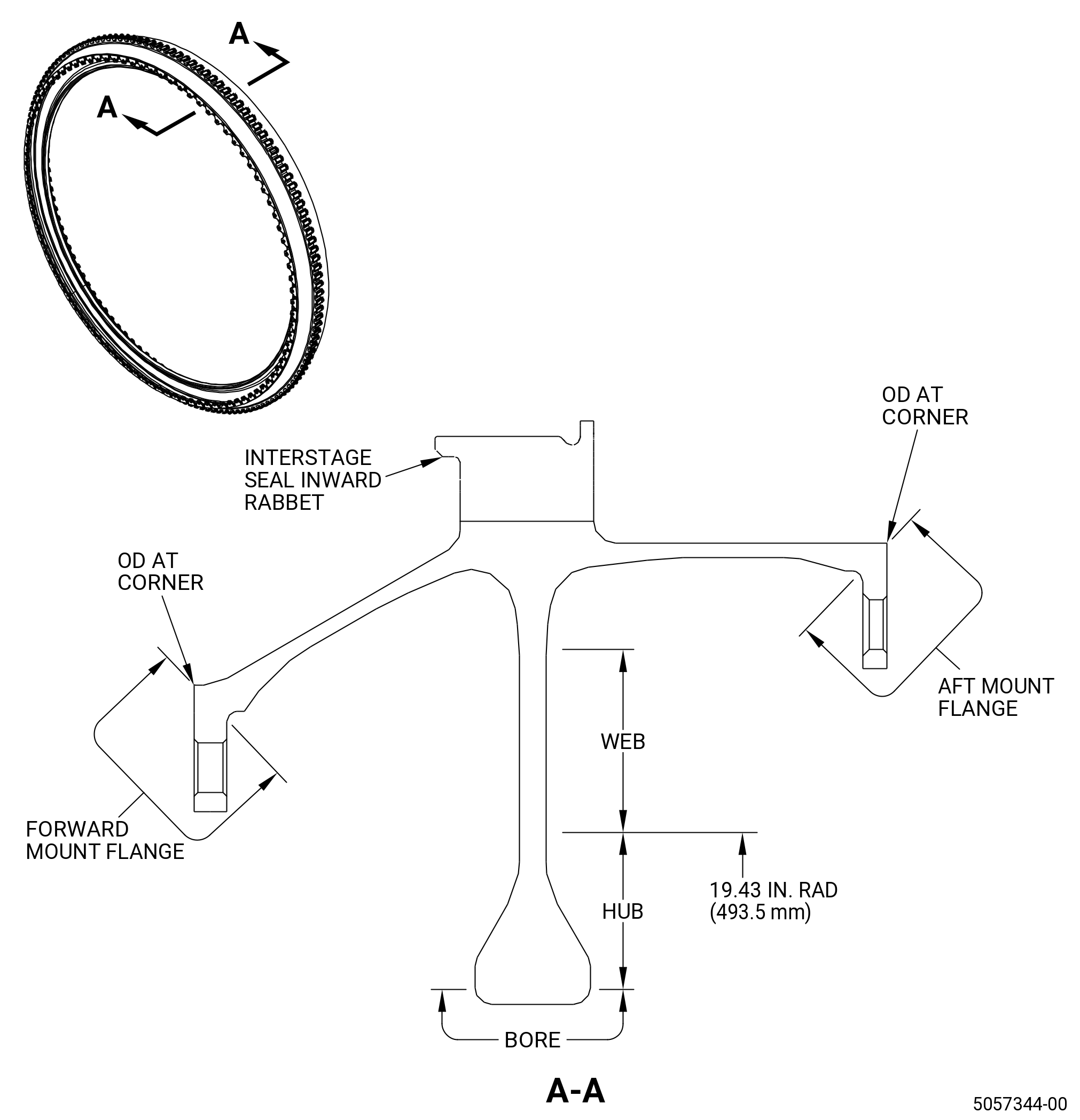
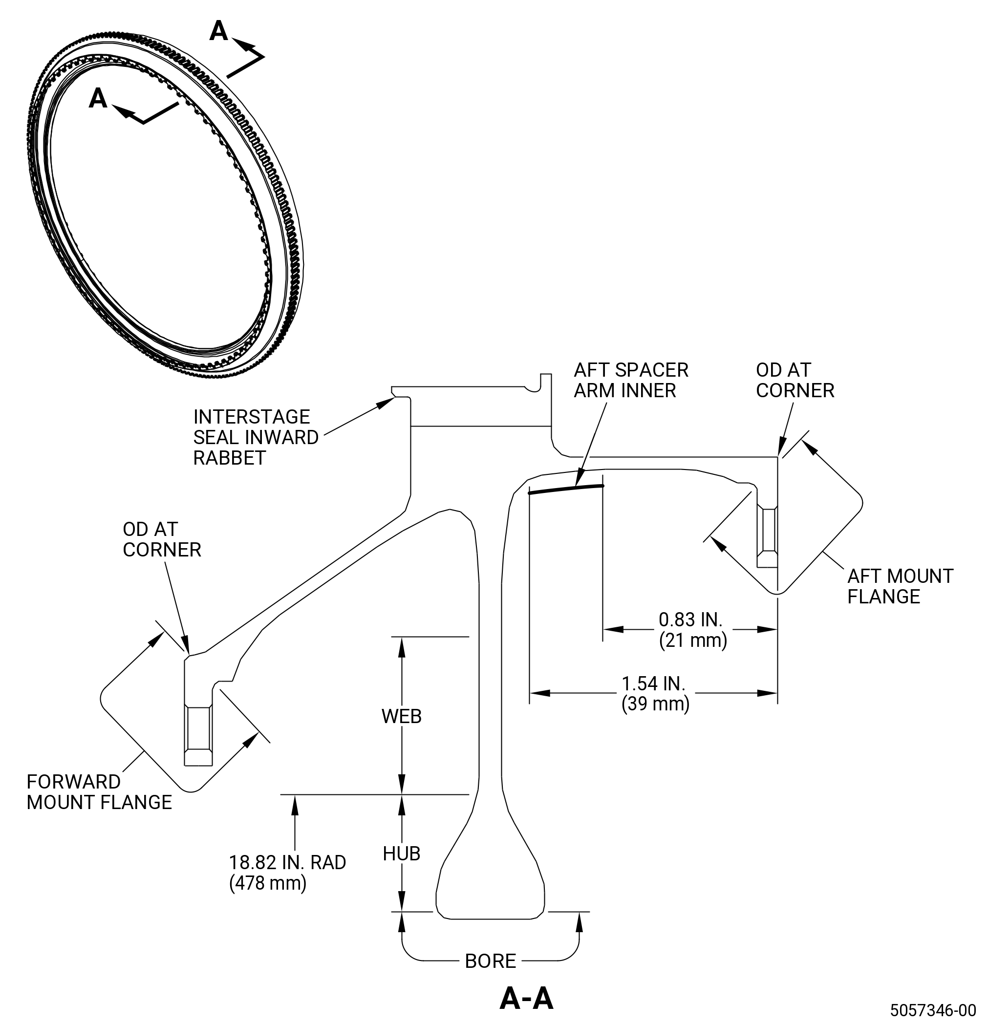
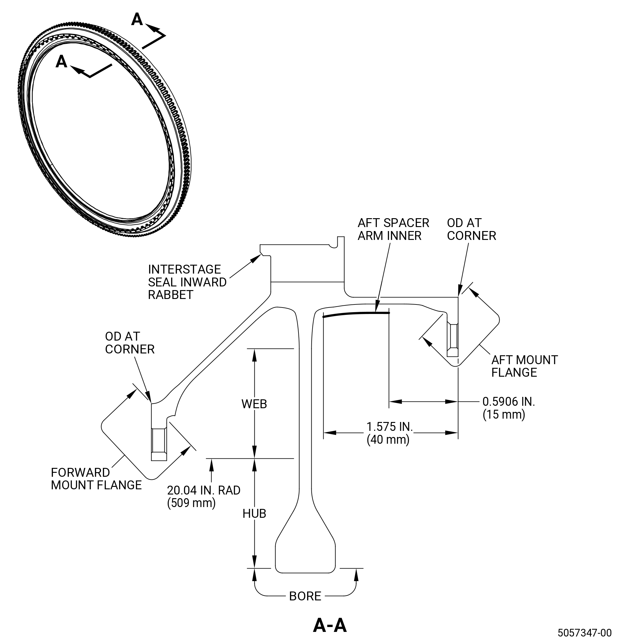
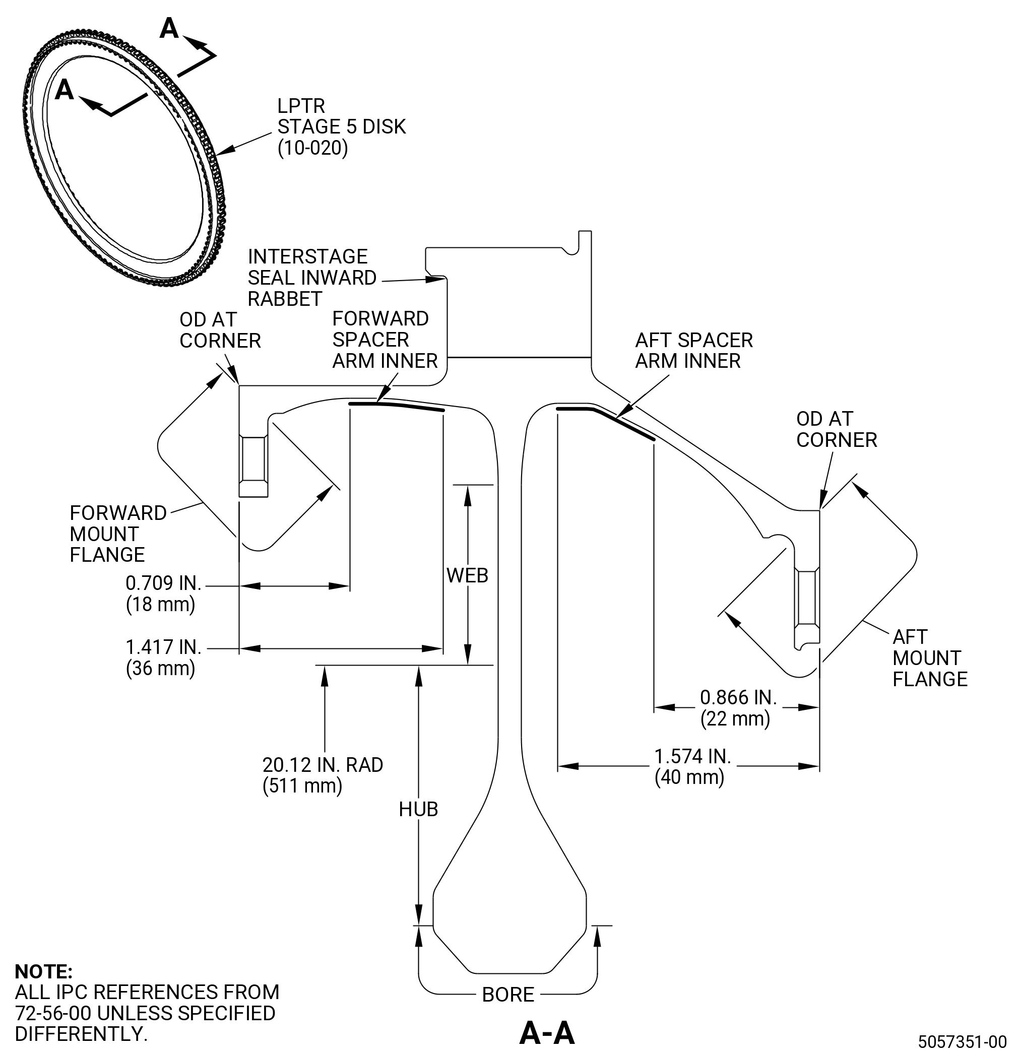
| AQ. | Do an inspection of the stage 1 to stage 5 disk bore for. Refer to Figure 811. |
| (1) | Cracks: |
| Maximum serviceable limit: |
|
| Repair method: |
|
| Subtask 72-00-04-220-182 |
| (2) | Nicks and scratches: |
| Maximum serviceable limit: |
|
| Repair method: |
|
| Subtask 72-00-04-220-183 |
| (3) | Dents: |
| Maximum serviceable limit: |
|
| Repair method: |
|
| Subtask 72-00-04-220-184 |
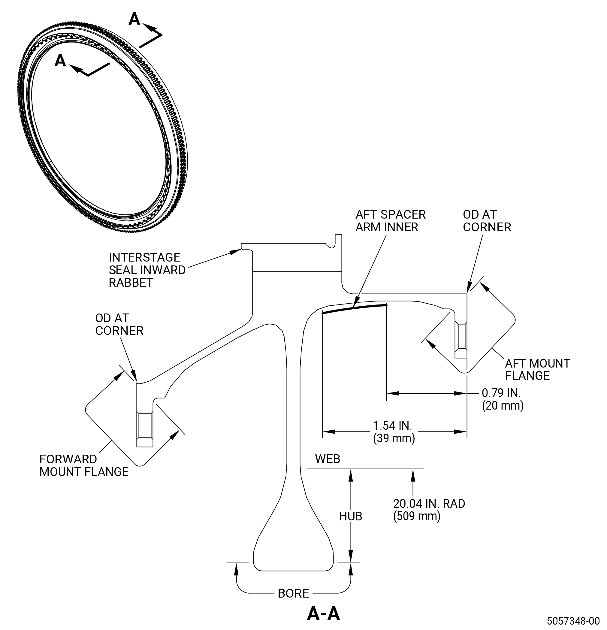
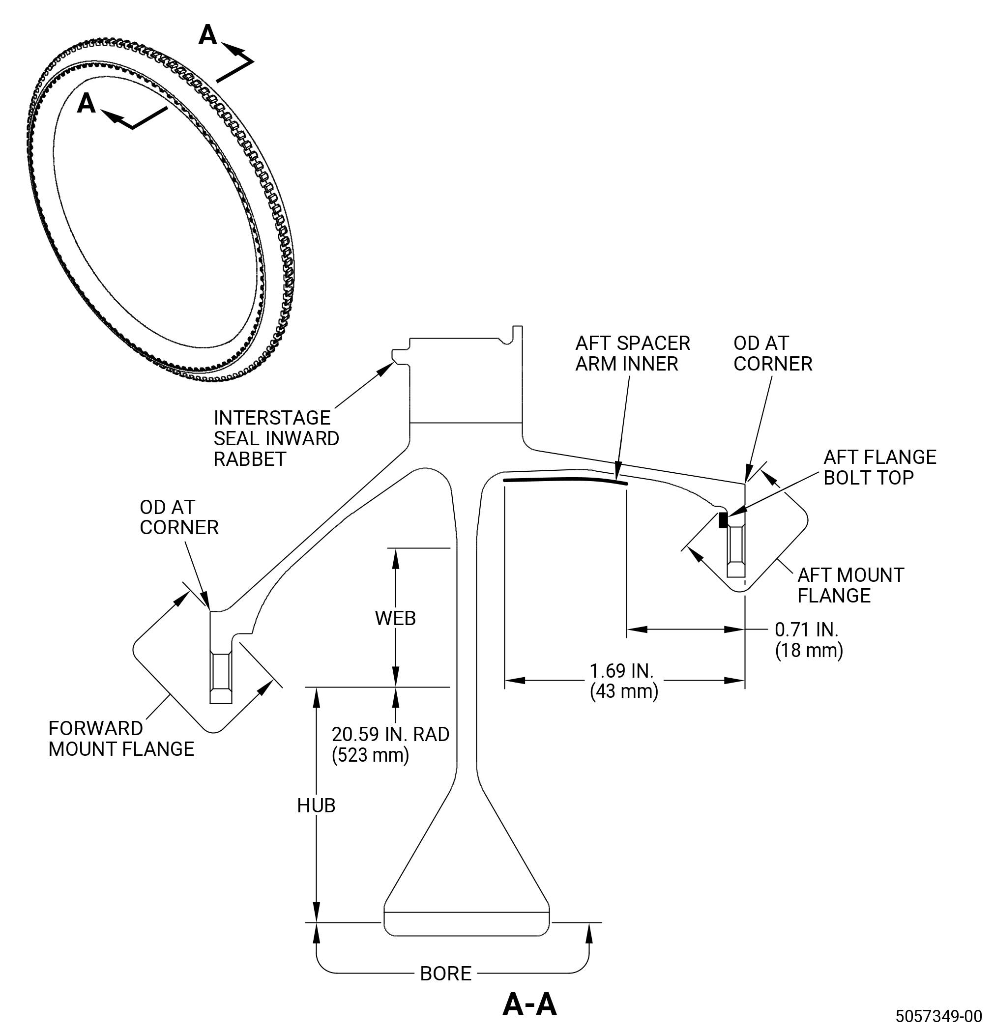
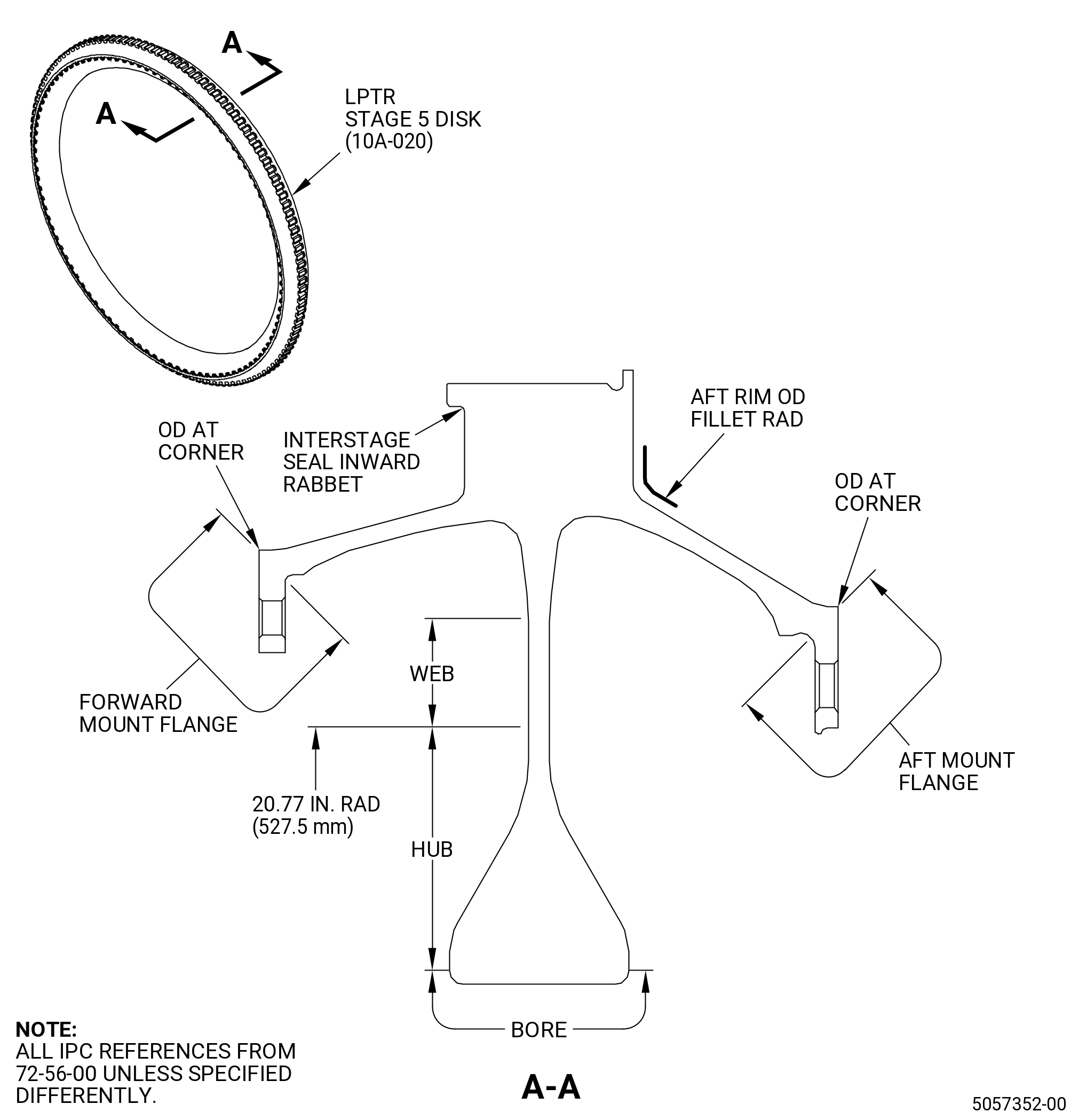
| AR. | Do an inspection of the stage 1, stage 2, stage 3 and stage 5 disk hub and web for. Refer to Figure 811. |
| (1) | Cracks: |
| Maximum serviceable limit: |
|
| Repair method: |
|
| Subtask 72-00-04-220-185 |
| (2) | Nicks and scratches: |
| Maximum serviceable limit: |
|
| Repair method: |
|
| Subtask 72-00-04-220-186 |
| (3) | Dents: |
| Maximum serviceable limit: |
|
| Repair method: |
|
| Subtask 72-00-04-220-187 |
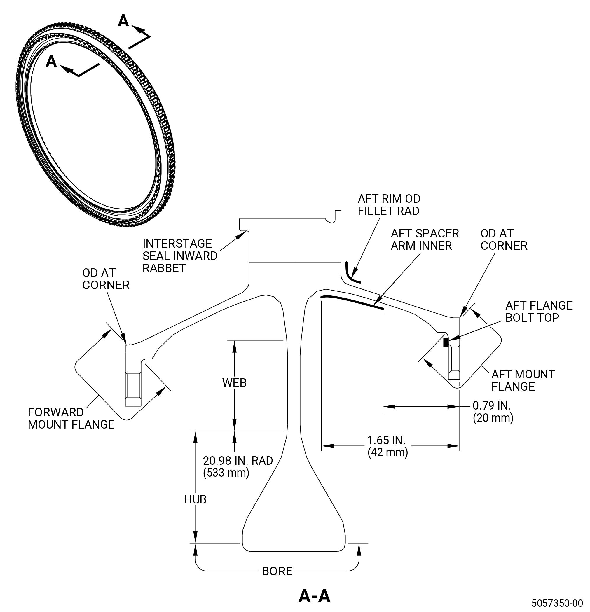
| AS. | Do an inspection of the stage 4 disk hub and web for. Refer to Figure 811. |
| (1) | Cracks: |
| Maximum serviceable limit: |
|
| Repair method: |
|
| Subtask 72-00-04-220-188 |
| (2) | Nicks and scratches: |
| Maximum serviceable limit: |
|
| Repair method: |
|
| Subtask 72-00-04-220-189 |
| * * * PRE SB 72-0040 |
| (3) | Dents for hub: |
| Maximum serviceable limit: |
|
| Repair method: |
|
| * * * END PRE SB 72-0040 |
| Subtask 72-00-04-220-190 |
| * * * SB 72-0040 |
| (3).A. | Dents for hub: |
| Maximum serviceable limit: |
|
| Repair method: |
|
| * * * END SB 72-0040 |
| Subtask 72-00-04-220-191 |
| (4) | Dents for web: |
| Maximum serviceable limit: |
|
| Repair method: |
|
| 5 . | Special Dimensional Inspection. |
| Subtask 72-00-04-220-035 |
| A. | Deleted. |
| 6 . | Determine the Serviceability of the Mid Fan Shaft Due to Rub. |
| Subtask 72-00-04-220-107 |
| A. | Do this procedure only if the visual inspection showed that there was damage specified as rub on the mid fan shaft (81000). |
| NOTE: |
|
| Subtask 72-00-04-250-001 |
| B. | Do a serviceability inspection of the mid fan shaft (81000). Refer to TASK 70-32-16-250-001 (SERVICEABILITY INSPECTION OF THE FAN MID SHAFT). |
| Subtask 72-00-04-380-002 |
| C. | If the paint was removed from the mid fan shaft (81000) to do the serviceability inspection, apply C03-038 Paint to the mid fan shaft. Refer to TASK 70-43-05-380-005 (INORGANIC ALUMINUM PROTECTIVE COATING). |
| Subtask 72-00-04-160-001 |
| WARNING: |
|
| WARNING: |
|
| D. | Acid etch areas of rub on the mid fan shaft (81000) as follows: |
| WARNING: |
|
| WARNING: |
|
| (1) | Prepare the solution in a plastic container. Fully mix 12-15 percent C04-072 Acid with 85-88 percent C04-035 Solvent. Keep the mixture covered when not in use. Use in less than 24 hours. |
| WARNING: |
|
| (2) | Clean the rubbed area with C04-003 Solvent . |
| WARNING: |
|
| (3) | Polish the rubbed area with emery cloth. Use grits of increasing fineness. The final polish must be done with emery cloth moistened with C04-003 Solvent. |
| CAUTION: |
|
| (4) | Apply the solution to the polished area with a cotton swab. Do not rub the solution on the shaft. Make sure the solution is not more than 24 hours old. The solution should fully cover the polished surface. Apply the solution for 2-3 minutes or until the area becomes very dark in color. The dark color shows that there is a rub condition. |
| (5) | Rinse the solution from the mid fan shaft with clean water and dry it with clean shop air or a cloth. |
| Subtask 72-00-04-220-036 |
| E. | Do a visual inspection of the etched area. |
| (1) | The mid fan shaft (81000) is serviceable if the color of the etched area is the same as the other areas of the fan mid shaft. |
| (2) | The mid fan shaft (81000) is not serviceable if the color of the etched area is lighter than the other areas of the fan mid shaft. |
| 7 . | Paint the Fan Mid Shaft. |
| Subtask 72-00-04-380-001 |
| A. | If the paint was removed from the mid fan shaft (81000) to do the visual inspection, apply C03-038 Paint to the mid fan shaft. Refer to TASK 70-43-05-380-005 (INORGANIC ALUMINUM PROTECTIVE COATING). |