| GENX-1B CLEANING,INSPECTION,AND REPAIR MANUAL | Dated: 12/05/2019 | |
| CIR 72-58-40 , REPAIR 009 | ||
| MID FAN SHAFT - REPAIR - BLEND AND SHOTPEEN REPAIR OF THE AREA B1 AND AREA F | ||
| GENX-1B CLEANING,INSPECTION,AND REPAIR MANUAL | Dated: 12/05/2019 | |
| CIR 72-58-40 , REPAIR 009 | ||
| MID FAN SHAFT - REPAIR - BLEND AND SHOTPEEN REPAIR OF THE AREA B1 AND AREA F | ||
| * * * FOR ALL |
| TASK 72-58-40-300-806 |
| 1 . | Blend and Shotpeen Repair of the Area B1 and Area F. |
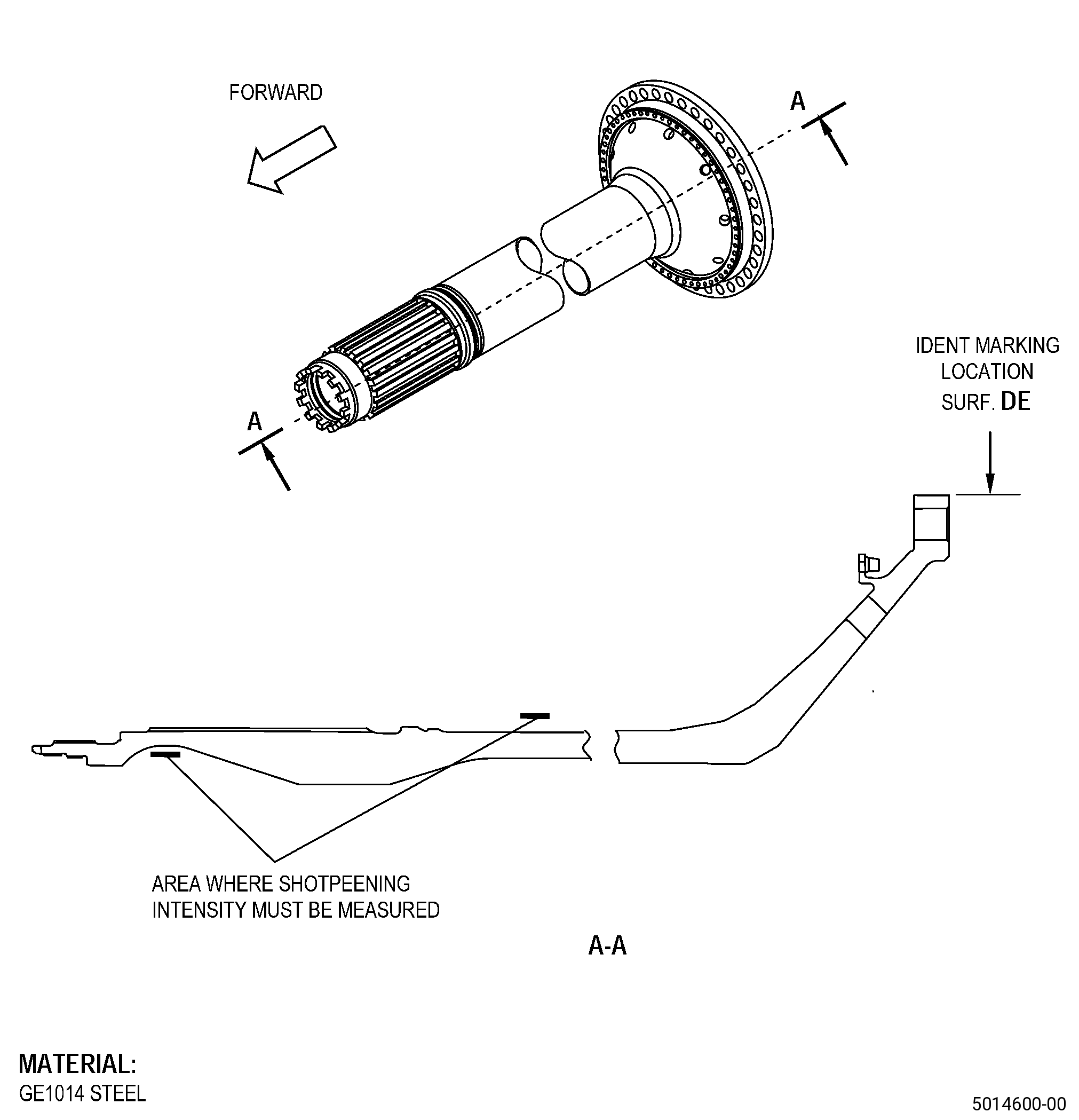
| A. | This procedure gives instructions to repair the mid fan shaft (shaft) by blending and shotpeening surface defects. Refer to Figure 901. |
| B. | The following maximum repairable limits apply to this repair: |
| NOTE: |
|
| NOTE: |
|
| (4) | Visual Inspection. |
| (p).A. | Do an inspection of the ID surface under the spline (area B1) for: |
| 1 | Deleted. |
| 2 | Nicks, dents, or scratches: |
| Maximum repairable limit: |
|
| 3 | Corrosion pit: |
| Maximum repairable limit: |
|
| (r) | Deleted. |
| (r).B. | Deleted. |
| (s) | Do an inspection of the OD surface (area F) for: |
| 2 | Nicks and dents on area F but not in area F3: |
| Maximum repairable limit: |
|
| 4 | Scratches on area F but not in area F3: |
| Maximum repairable limit: |
|
| C. | The subsequent table gives a list of the part numbers that are applicable to this repair. All part numbers are applicable to all paragraphs unless specified differently. |
|
||||||||||||||||||||||||||||||||||||
| D. | Proprietary/Complex Process Statement. |
| (1) | None. |
| 2 . | Tools, Equipment, and Materials. |
| NOTE: |
|
| A. | Tools and Equipment. |
| (1) | Special Tools. None. |
| (2) | Standard Tools and Equipment. None. |
| (3) | Locally Manufactured Tools. None. |
| B. | Consumable Materials. |
|
| C. | Referenced Procedures. |
| D. | Expendable Parts. None. |
| E. | SPD Information. |
| (1) | Locally Manufactured SPD. None. |
| F. | Special Solutions. None. |
| G. | Test Specimens. None. |
| 3 . | Dimensional Information. |
| Subtask 72-58-40-220-095 |
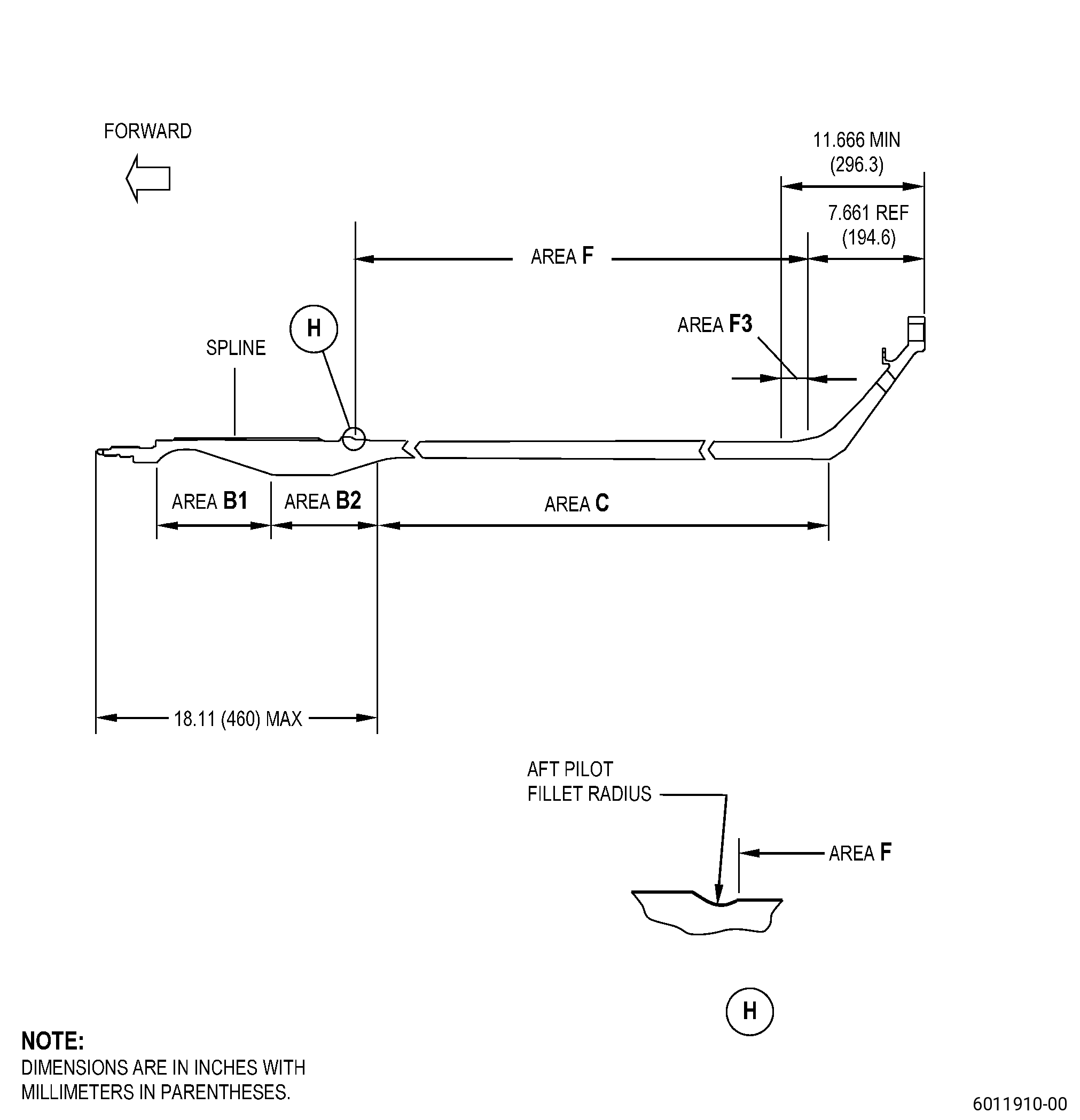
| A. | Refer to Figure 901 for specified dimensions and locations. |
| NOTE: |
|
| NOTE: |
|
| 4 . | Setup Information. |
| None. |
| 5 . | Procedure. |
| Subtask 72-58-40-380-010 |
| CAUTION: |
|
| A. | After you complete this repair procedure, make sure that you apply protective coating to the shaft in less than 24 hours after you remove it. If you cannot apply protective coating in less than 24 hours, apply preservative oil. Refer to TASK 72-58-00-550-801 (72-58-00, STORAGE 001). |
| Subtask 72-58-40-160-003 |
| B. | If necessary, clean the shaft. Refer to TASK 72-58-40-100-801 (72-58-40, CLEANING 001). |
| Subtask 72-58-40-210-002 |
| C. | Do a check of the shaft to find a repair mark R009. Refer to Figure 901 and as follows: |
| NOTE: |
|
| NOTE: |
|
| (1) | If there is a repair mark R009 adjacent to the part number, the part cannot be repaired by this procedure. Remove the shaft from service and contact a GE Representative. |
| (2) | If there is no repair mark adjacent to the part number, refer to Subtask 72-58-40-350-033 (paragraph 5.D.). |
| Subtask 72-58-40-350-033 |
| CAUTION: |
|
| D. | Blend the shaft. Refer to TASK 70-42-00-350-002 (BLENDING AND REMOVAL OF HIGH METAL PROCEDURES), Figure 901, Figure 902, and as follows: |
| (1) | Blend the shaft to remove damaged or defective material in area B1 and area F (but not in area F3) only. |
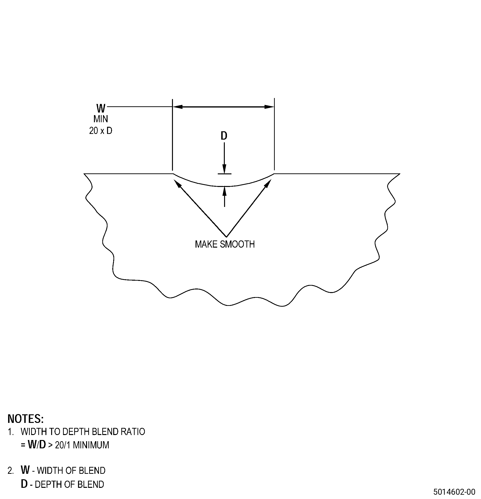
| (2) | The width of the blend must be a minimum of 20 times its depth. You must measure the width as the shortest distance across the edge of the blended area. |
| (3) | The maximum blend depth is 0.0098 inch (0.25 mm). |
| (4) | Blending into area B2 is not permitted. |
| (5) | Blending is not permitted on the aft pilot fillet radius. |
| (6) | Blending in area F3 is not permitted. |
| Subtask 72-58-40-220-096 |
| E. | Do an inspection of the shaft blended areas. Refer to TASK 72-58-40-200-801 (72-58-40, INSPECTION 001), Figure 901, Figure 902, and as follows: |
| (1) | Make sure that you removed all defects and that the dimensions of the blended areas agree with the limits of Subtask 72-58-40-350-033 (paragraph 5.D.). |
| Subtask 72-58-40-240-003 |
| F. | Do a magnetic particle inspection of the blended area. Refer to TASK 72-58-40-200-801 (72-58-40, INSPECTION 001). |
| Subtask 72-58-40-380-011 |
| CAUTION: |
|
| G. | Alternative Procedure Available. Peen the shaft repair area. Refer to TASK 70-47-01-380-016 (SHOTPEENING), Figure 901, and as follows: |
| (1) | Apply C10-021 plastic tape to the inner and outer threads, thermal spray coating, and adjacent surfaces that you will not peen. |
| (2) | Overspray on the adjacent area is permitted, if peening is permitted on the area. |
| (3) | Peening intensity must decrease gradually in the overspray area and there must be a smooth transition between the peened and non-peened areas. |
| (4) | Use S-170 maximum cast steel shot, with a hardness of 55-65 HRc. |
| (5) | Peening intensity must be 0.010-0.015A. |
| (6) | A minimum coverage of 100 percent is necessary. |
| (7) | Remove the masking from the shaft. |
| Subtask 72-58-40-380-012 |
| CAUTION: |
|
| CAUTION: |
|
| G.A. | Alternative Procedure. Peen the shaft repair area. Refer to TASK 70-47-04-380-019 (ROTARY FLAP PEENING), Figure 901, and as follows: |
| (1) | Apply C10-021 plastic tape to the inner and outer threads, thermal spray coating, and adjacent surfaces that you will not peen. |
| (2) | Peening on the adjacent area is permitted, if peening is permitted on the area. |
| (3) | Peening intensity must decrease gradually in the overspray area and there must be a smooth transition between the peened and non-peened areas. |
| (4) | Peening intensity must be 0.010-0.015A. |
| (5) | Do an intensity verification as follows: |
| (a) | Use a magnetic Almen strip holder. |
| NOTE: |
|
| (b) | Make sure that you do the intensity verification with 0.014-0.021A. |
| NOTE: |
|
| (6) | A minimum coverage of 100 percent is necessary. |
| (7) | Remove the masking from the shaft. |
| Subtask 72-58-40-350-034 |
| H. | Put a mark on surface DE of the shaft. Refer to TASK 70-16-00-350-001 (MARKING PRACTICES), TASK 70-16-08-350-001 (DOT PEEN MARKING FOR OPTICAL CHARACTER RECOGNITION), Figure 901, and as follows: |
| (1) | Put a mark of the repair number R009 adjacent to the part number on the shaft. Use the same font size. |
| (2) | Use method 1 or method 2. |
| Subtask 72-58-40-350-035 |
| I. | Complete all the necessary repairs for the shaft. |
| Subtask 72-58-40-380-013 |
| J. | Apply the protective coatings and do a balance inspection of the shaft as follows: |
| (1) | For part numbers 2331M20G02, 2331M20G03, 2332M81G03, and 2332M81G04. Refer to TASK 72-58-40-200-801 (72-58-40, INSPECTION 001), TASK 72-58-40-300-803 (72-58-40, REPAIR 002), and TASK 72-58-40-300-804 (72-58-40, REPAIR 003). |
| (2) | For part numbers 2332M81G05, 2440M20G05, 2440M91G05, and 2440M91G06. Refer to TASK 72-58-40-200-801 (72-58-40, INSPECTION 001), TASK 72-58-40-300-804 (72-58-40, REPAIR 003), and TASK 72-58-40-300-812 (REPAIR 013). |