| GENX-1B CLEANING,INSPECTION,AND REPAIR MANUAL | Dated: 10/31/2019 | |
| CIR 72-58-40 , REPAIR 011 | ||
| MID FAN SHAFT - REPAIR - THERMAL SPRAY REPAIR ON THE AFT PILOT OUTER DIAMETER | ||
| GENX-1B CLEANING,INSPECTION,AND REPAIR MANUAL | Dated: 10/31/2019 | |
| CIR 72-58-40 , REPAIR 011 | ||
| MID FAN SHAFT - REPAIR - THERMAL SPRAY REPAIR ON THE AFT PILOT OUTER DIAMETER | ||
| * * * FOR ALL |
| TASK 72-58-40-300-809 |
| 1 . | Thermal Spray Repair On The Aft Pilot Outer Diameter. |
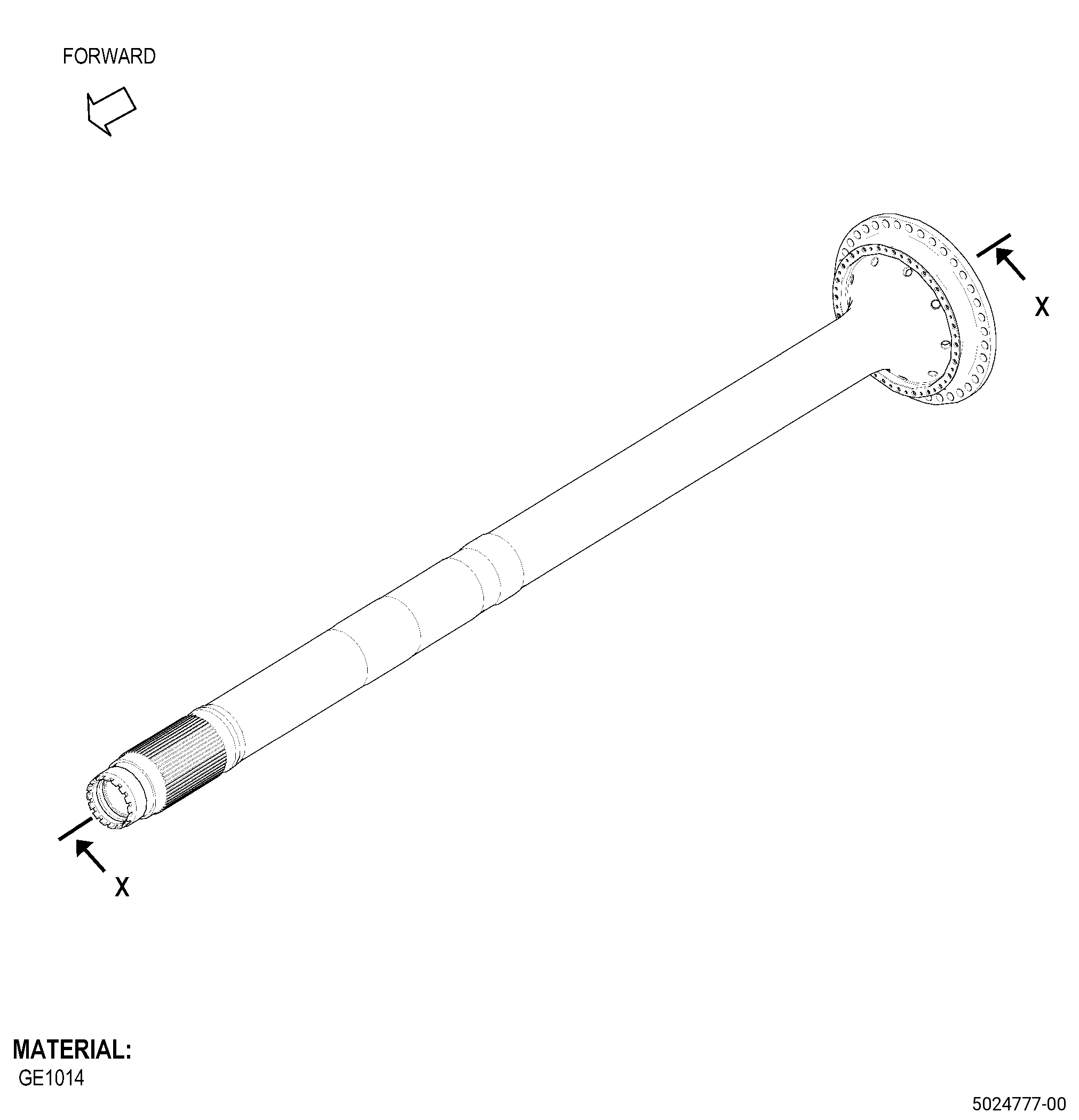
| A. | This procedure gives instructions to repair the mid fan shaft (shaft) by thermal spraying the aft pilot outer diameter. Refer to Figure 901. |
| B. | The following maximum repairable limits apply to this repair: |
| NOTE: |
|
| (4) | Visual Inspection. |
| (i) | Do an inspection of the aft pilot outer diameter for: |
| 2 | Nicks, dents, and scratches: |
| Maximum repairable limit: |
|
| 3 | Wear or galling: |
| Maximum repairable limit: |
|
| C. | The subsequent table gives a list of the part numbers that are applicable to this repair. All part numbers are applicable to all paragraphs unless specified differently. |
|
||||||||||||||||||||||||||||||||||||
| D. | Proprietary/Complex Process Statement. |
| (1) | None. |
| 2 . | Tools, Equipment, and Materials. |
| NOTE: |
|
| A. | Tools and Equipment. |
| (1) | Special Tools. None. |
| (2) | Standard Tools and Equipment. None. |
| (3) | Locally Manufactured Tools. None. |
| B. | Consumable Materials. |
|
| C. | Referenced Procedures. |
| D. | Expendable Parts. None. |
| E. | SPD Information. |
| (1) | Locally Manufactured SPD. None. |
| F. | Special Solutions. None. |
| G. | Test Specimens. Refer to TASK 70-49-21-340-022 (THERMAL SPRAYING NICKEL-CHROMIUM/ALUMINUM COMPOSITE (POWDER)) . |
| 3 . | Dimensional Information. |
| Subtask 72-58-40-220-120 |
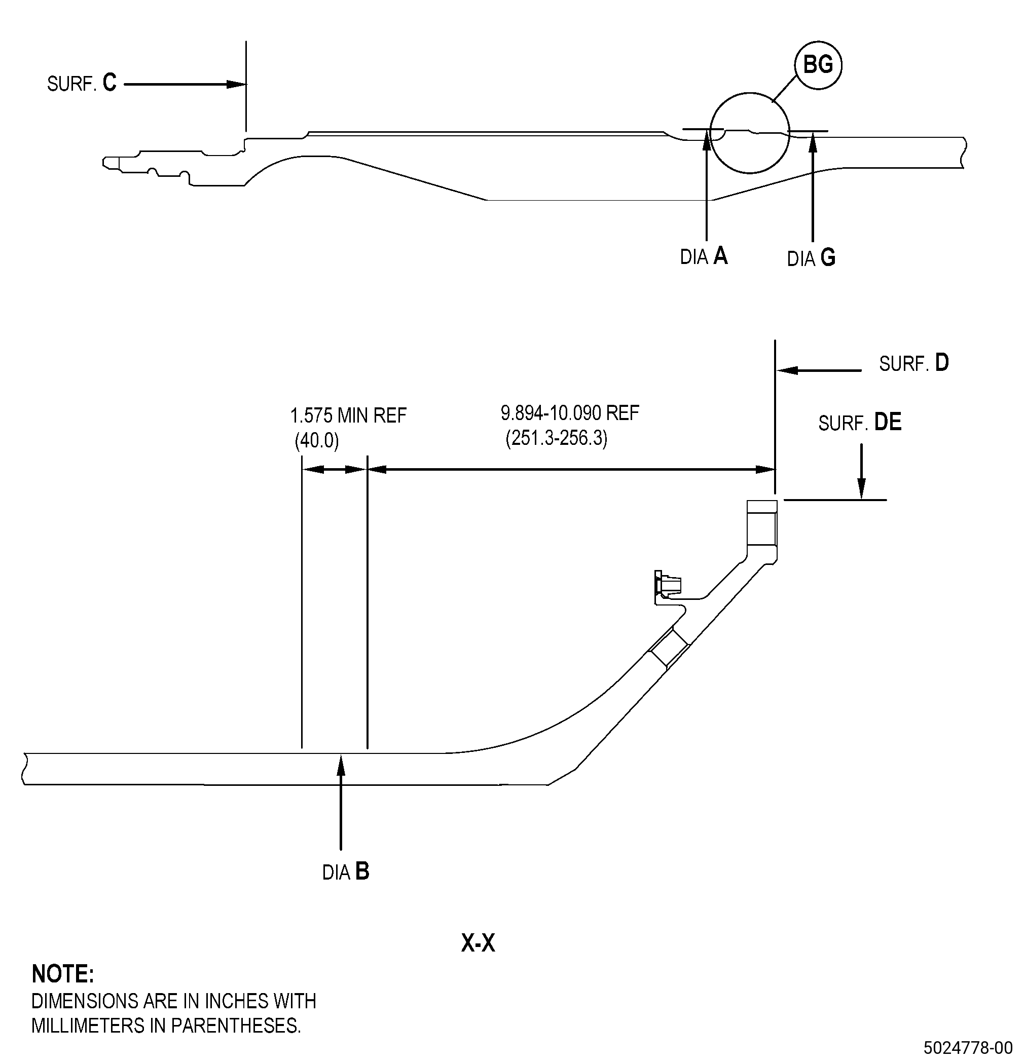
| A. | Refer to Figure 901, Figure 902, Figure 903, and Figure 905 for specified dimensions and locations. |
| NOTE: |
|
| NOTE: |
|
|
| 4 . | Setup Information. |
| Subtask 72-58-40-350-043 |
| A. | Set-up the shaft for machining. Refer to Figure 901 and do as follows: |
| Subtask 72-58-40-220-121 |
| (1) | Set diameter G to a maximum of 0.00019 inch (0.005 mm) and diameter B to a maximum of 0.00039 inch (0.010 mm) concentric with machine axis. |
| 5 . | Procedure. |
| Subtask 72-58-40-160-005 |
| CAUTION: |
|
| A. | If necessary, clean the shaft. Refer to TASK 72-58-40-100-801 (72-58-40, CLEANING 001). |
| Subtask 72-58-40-320-010 |
| CAUTION: |
|
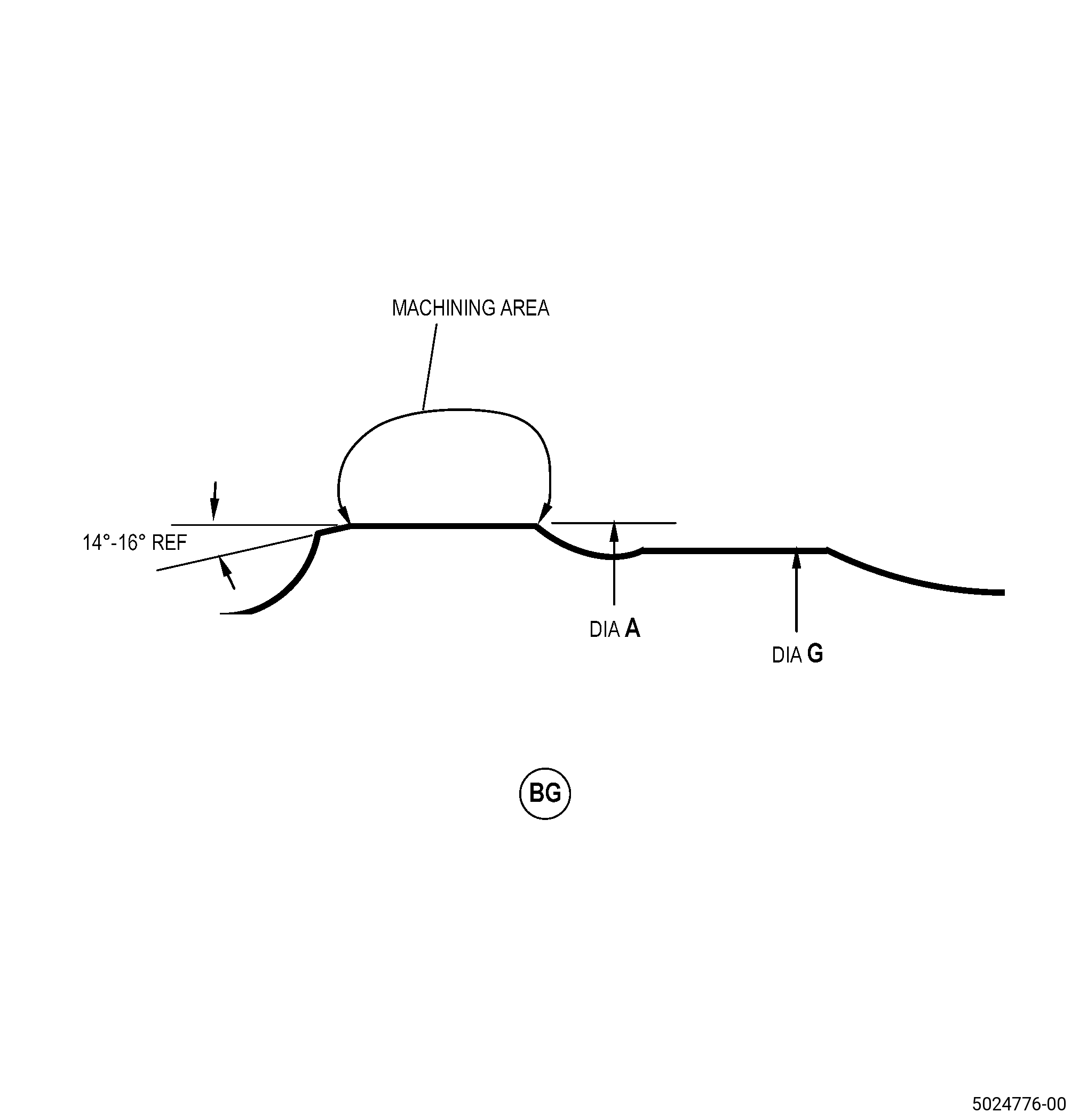
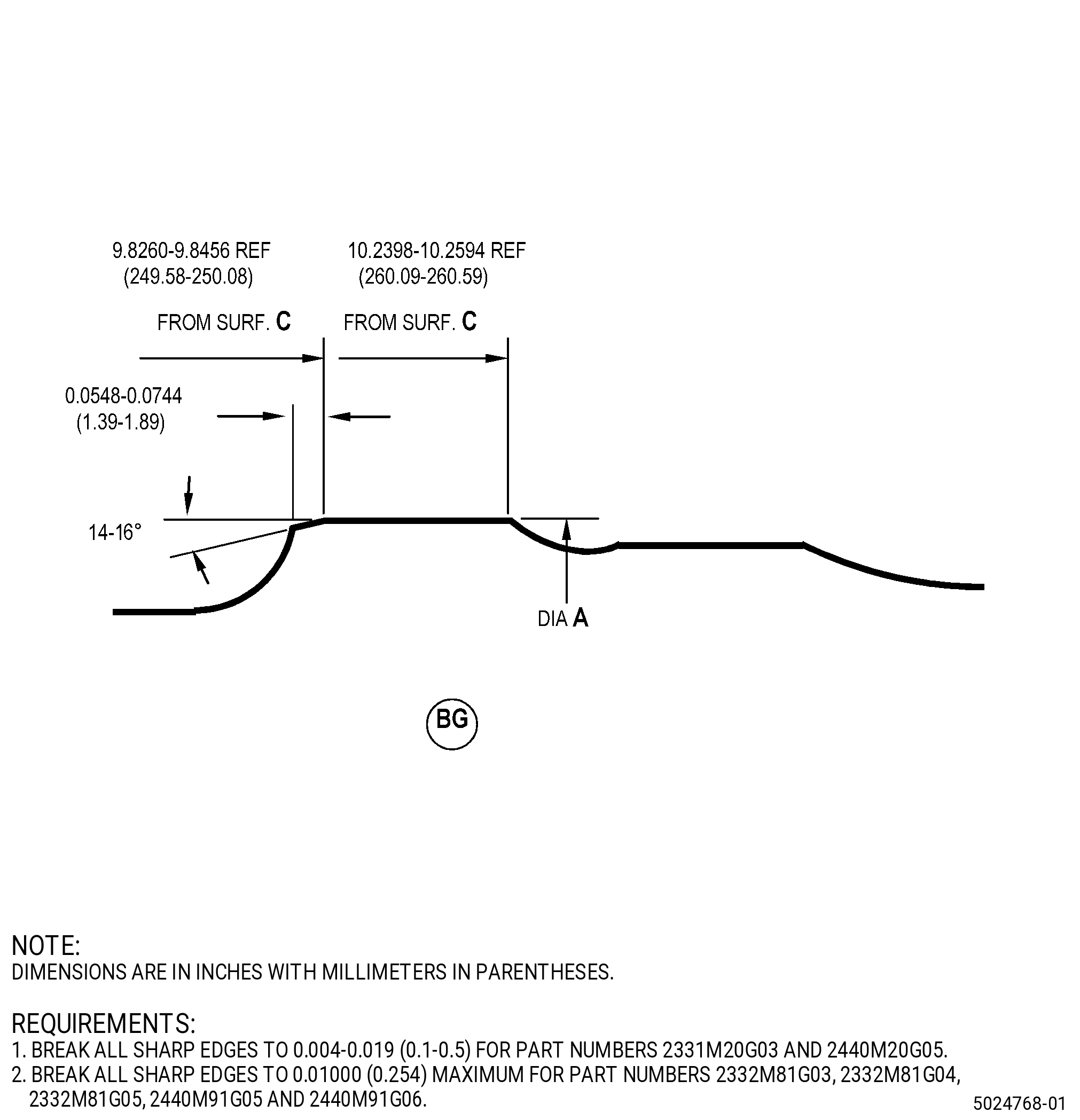
| B. | Machine the shaft diameter A. Refer to TASK 70-00-03-800-004 (MACHINING DATA), Subtask 72-58-40-220-120 (paragraph 3.A.), Figure 901, Figure 902, and as follows: |
| (1) | For tolerances and general instructions, which include visual inspection after machining. Refer to TASK 70-31-06-220-001 (MACHINED FEATURES SHOP-RUN TOLERANCES). |
| (2) | Set-up the shaft for machining. Refer to Subtask 72-58-40-350-043 (paragraph 4.A.). |
| (3) | Machine the shaft diameter A to the in-process dimensions to remove all damage/remaining thermal spray coating. |
| (4) | Break all sharp edges to 0.00500-0.01500 inch (0.127-0.381 mm). |
| Subtask 72-58-40-220-126 |
| C. | Do a dimensional inspection of the shaft machined area. Refer to Subtask 72-58-40-220-120 (paragraph 3.A.), Figure 902, and as follows: |
| (1) | If diameter A does not agree with the in-process dimensions, you cannot repair the shaft with this procedure. |
| Subtask 72-58-40-160-006 |
| D. | Clean the shaft machined area. Refer to TASK 70-21-00-110-051 (CHEMICAL CLEANING) and TASK 70-21-03-160-001 (CLEANING METHOD NO. 3 - STEAM CLEANING). |
| Subtask 72-58-40-240-006 |
| E. | Do a magnetic-particle inspection of the shaft machined area. Refer to TASK 72-58-40-200-801 (72-58-40, INSPECTION 001) and as follows: |
| (1) | Indications are not permitted. |
| Subtask 72-58-40-380-018 |
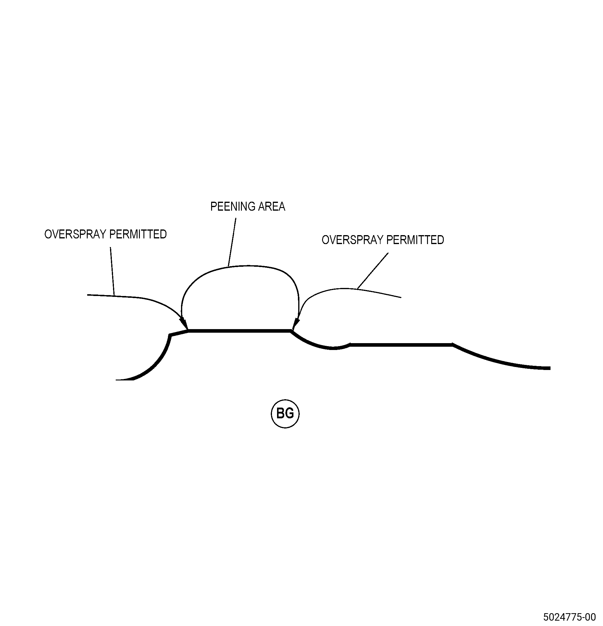
| F. | Peen the shaft machined area. Refer to TASK 70-47-01-380-016 (SHOTPEENING), Figure 903 and as follows: |
| (1) | If necessary, clean the shaft machined area. Refer to TASK 70-21-00-110-051 (CHEMICAL CLEANING) and TASK 70-21-23-110-053 (CLEANING METHOD NO. 23 - HAND-WIPE DEGREASING). |
| (2) | Use S170 maximum C04-271 high hardness cast steel shot. |
| (3) | Shot media hardness must be 55-65 HRc. |
| (4) | Intensity must be 0.010-0.015A. |
| (5) | Use a scrap or simulative fixture. |
| (6) | Shotpeen overspray is permitted but not on the diameter G, splines, threaded or coated areas. |
| (7) | Minimum of 100 percent coverage is required. |
| Subtask 72-58-40-340-002 |
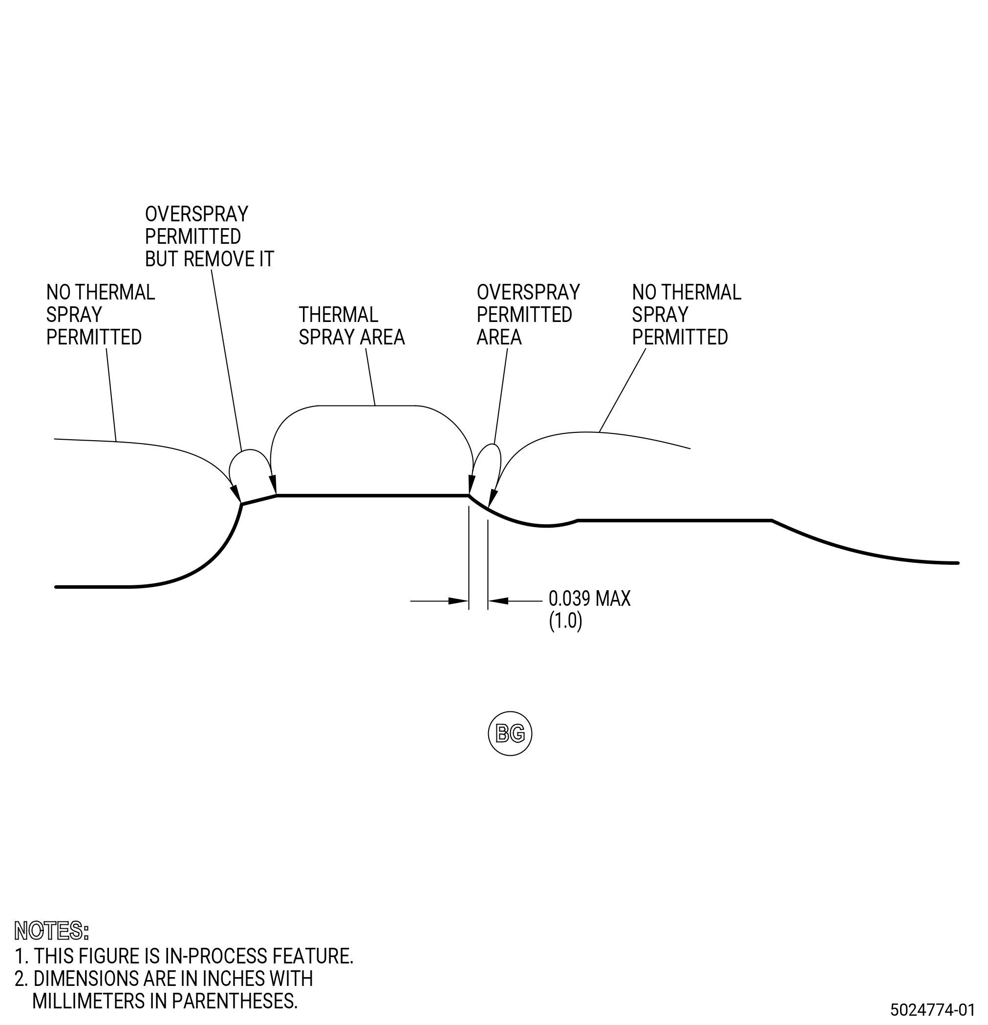
| G. | Thermal-spray the shaft machined areas and the test specimens. Refer to TASK 70-49-00-340-001 (THERMAL SPRAYING), TASK 70-49-21-340-022 (THERMAL SPRAYING NICKEL-CHROMIUM/ALUMINUM COMPOSITE (POWDER)), Figure 904, and as follows: |
| (1) | Maximum as sprayed coating thickness must not be more than 0.039 inch (1.0 mm). |
| Subtask 72-58-40-320-012 |
| H. | Machine the shaft to the finish dimensions. Refer to TASK 70-00-03-800-004 (MACHINING DATA), Subtask 72-58-40-220-120 (paragraph 3.A.), Figure 901, Figure 905, and as follows: |
| (1) | For tolerances, refer to TASK 70-31-06-220-001 (MACHINED FEATURES SHOP-RUN TOLERANCES). |
| (2) | Set-up the shaft for machining. Refer to Subtask 72-58-40-350-043 (paragraph 4.A.). |
| (3) | Machine diameter A to the finish dimensions. |
| (4) | The repair area surface finish must be 32 microinches (0.8 micrometers) or better. |
| (5) | Remove the sharp edges as necessary. |
| Subtask 72-58-40-350-047 |
| CAUTION: |
|
| I. | Blend the shaft. Refer to TASK 70-42-00-350-002 (BLENDING AND REMOVAL OF HIGH METAL PROCEDURES), Figure 905, and do as follows: |
| NOTE: |
|
| (1) | Make sure that you remove all burrs and sharp edges from the repaired area. |
| (2) | Make a smooth contour of the thermal sprayed area with the adjacent surface. |
| (3) | Maximum blend depth of base metal at overspray coating removal is 0.00098 inch (0.025 mm). |
| Subtask 72-58-40-220-127 |
| J. | Do a dimensional inspection of the shaft repaired area. Refer to Subtask 72-58-40-220-120 (paragraph 3.A.) and Figure 905. |
| Subtask 72-58-40-220-125 |
| K. | Do a visual inspection of the shaft repaired area as follows: |
| (1) | Spalling, chipping, cracking, or separation of the thermal spray coating or oversprayed coating is not permitted. |
| (2) | If you find defects, do Subtask 72-58-40-320-010 (paragraph 5.B.) thru Subtask 72-58-40-220-125 (paragraph 5.K.) again. |
| Subtask 72-58-40-220-128 |
| L. | Measure the runout of the shaft. Refer to Figure 901 and do as follows: |
| (1) | Measure the runout of surface D with respect to diameter A and diameter B. |
| (2) | If the position of the lowest measured runout point is different from the position of the mark L on surface DE, do Subtask 72-58-40-350-048 (paragraph 5.M.). |
| (3) | If the position of the lowest measured runout point is the same position of the mark L on surface DE, refer to Subtask 72-58-40-350-049 (paragraph 5.N.). |
| Subtask 72-58-40-350-048 |
| M. | If necessary, put a mark on the shaft. Refer to TASK 70-16-00-350-001 (MARKING PRACTICES), TASK 70-16-08-350-001 (DOT PEEN MARKING FOR OPTICAL CHARACTER RECOGNITION), and as follows: |
| NOTE: |
|
| (1) | Use Method 1 or Method 2 as follows: |
| (a) | Character height is 0.0603-0.1200 inch (1.53-3.05 mm). |
| (2) | Put a line through the mark L on the mounting flange outer diameter of surface DE. |
| (3) | Put a mark L on surface DE at the lowest runout point of surface D that you recently measured. |
| Subtask 72-58-40-350-049 |
| N. | Complete all the necessary repairs for the shaft. |
| Subtask 72-58-40-350-050 |
| O. | Do a balance inspection of the shaft and correct imbalance as necessary. Refer to TASK 72-58-40-300-801 (72-58-40, REPAIR 001). |
| NOTE: |
|
| Subtask 72-58-40-350-051 |
| P. | Apply protective paint to the shaft, as follows: |
| (1) | For part numbers 2331M20G03 , 2332M81G03 , and 2332M81G04 , apply protective paint to the shaft. Refer to TASK 72-58-40-300-803 (72-58-40, REPAIR 002). |
| (2) | For part numbers 2332M81G05 , 2440M20G05 , 2440M91G05 , and 2440M91G06 , apply protective paint and seal coat to the shaft. Refer to TASK 72-58-40-300-812 (72-58-40, REPAIR 013). |
| Subtask 72-58-40-350-052 |
| Q. | Apply solid film lubricant to the shaft. Refer to TASK 72-58-40-300-804 (72-58-40, REPAIR 003). |
| Subtask 72-58-40-350-053 |
| R. | Apply oil to the shaft surface where solid dry film lubricant or aluminum protective paint is not applied. Refer to TASK 72-58-00-550-801 (72-58-00, STORAGE 001) for approved oils. |